64
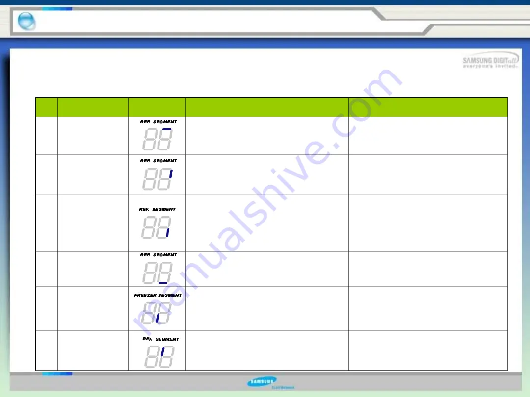
4-5. Self-Diagnostics Function
NO
Error items
LED Display
Details
Remarks
01
ICE MAKER
SENSOR
Ice Maker sensor connector missing;
contact failure, electric wire cut, short-
circuit; Ice Maker sensor failure; and so on
The voltage should be within the range of
4. 5V~1.0V between MAIN PCB CN90 # 3
and # 4.
02
REFRIGERATOR
SENSOR
Refrigerator sensor connector missing;
contact failure, electric wire cut, short-
circuit; Refrigerator sensor itself failure;
and so on
The voltage should be within the range of
4.5V~1.0V between MAIN PCB CN30 # 6
and # 7.
03
REFRIGERATOR
DEFROST
SENSOR
Refrigerator evaporator internal defrosting
sensor connector missing; contact failure,
electric wire cut, short-circuit; sensor itself
failure; and so on
The voltage should be within the range of
4.5V~1.0V between MAIN PCB
CN30 # 6 and # 8.Indicate Error when the
temperature sensed by Refrigerator
defrosting sensor is higher than 65.5
℃
or
lower than
–
58
℃
.
04
REFRIGERATOR
FAN ERROR
Refrigerator Fan motor operation failure;
feedback signal line contact failed, electric
wire cut, short- circuit; and so on
The voltage should be 7V~12V between
MAIN PCB CN72 #5(ORANGE) and
#7(GRAY).
05
ICE MAKER
function
ERROR
Ice-ejector and level failed three times or
more
Push the test button, Ice Maker should
work.
06
CoolSelect
ZoneTM sensor
CoolSelect Zone
TM
sensor connector
missing; contact failed, electric wire cut,
short-circuit; CoolSelect ZoneTM sensor
itself failed; and so on.
The voltage should be within the range of
4.5V~1.0V between MAIN PCB CN51 # 13
and # 14.
Error items of self-diagnostics
4.
Troubleshooting and major adjustment
Summary of Contents for RS277ACPN
Page 14: ...15 1 7 Dimensions of Refrigerator inches 1 Product Information...
Page 17: ...18 1 10 Cooling Air Circulation 1 Product Information Freezer Refrigerator...
Page 70: ...71 5 1 Block diagram 5 Circuit Descriptions Double Click...
Page 71: ...72 5 2 SCHEMATIC DIAGRAM 5 Circuit Descriptions Double Click...
Page 72: ...73 5 3 WIRING DIAGRAM 5 Circuit Descriptions Double Click...
Page 74: ...75 5 5 CONNECTOR ARRANGEMENT Main Board 5 Circuit Descriptions Double Click...
Page 87: ...88 5 17 Load Drive Circuit 5 Circuit Descriptions Double Click...
Page 92: ...93 6 Reference Information 6 2 Model name nomenclature...
Page 93: ...94 The End Thank you...


