78
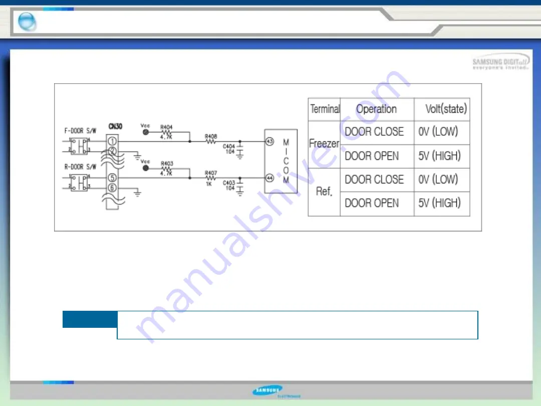
5-9. Door S/W Sensing Circuit
5. Circuit Descriptions
1) The terminals,
②
and
⑥
of the connector (CN30) are grounded, and DC5V (Vcc) is
supplied to the terminals,
⑤
and
⑥
through the resistors, R404 and R403 for the freezer
and the refrigerator door, respectively.
2) The micro-processor senses the door’s open and close based on engaged voltages,
“Low(0V)” and “High(5V),” respectively.
The door switch always should be checked when the evaporator fan is not
running while the door is closed.
Note
Summary of Contents for RS277ACPN
Page 14: ...15 1 7 Dimensions of Refrigerator inches 1 Product Information...
Page 17: ...18 1 10 Cooling Air Circulation 1 Product Information Freezer Refrigerator...
Page 70: ...71 5 1 Block diagram 5 Circuit Descriptions Double Click...
Page 71: ...72 5 2 SCHEMATIC DIAGRAM 5 Circuit Descriptions Double Click...
Page 72: ...73 5 3 WIRING DIAGRAM 5 Circuit Descriptions Double Click...
Page 74: ...75 5 5 CONNECTOR ARRANGEMENT Main Board 5 Circuit Descriptions Double Click...
Page 87: ...88 5 17 Load Drive Circuit 5 Circuit Descriptions Double Click...
Page 92: ...93 6 Reference Information 6 2 Model name nomenclature...
Page 93: ...94 The End Thank you...


