TROUBLE SHOOTING
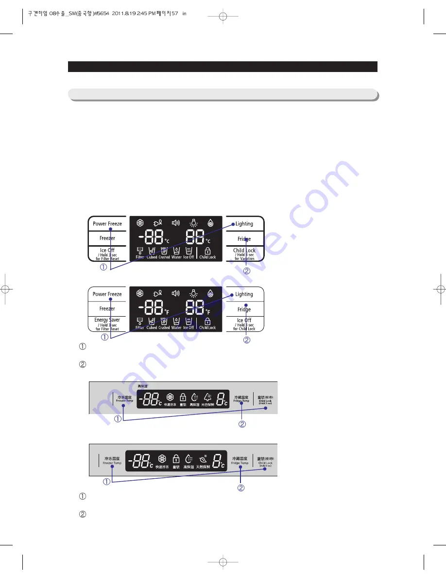
1) When the Power Freezer and the Lighting buttons(Freezer Temp and Child Lock buttoms for RSG5B*
Model) are held down together for 6 seconds during the normal operation, the Fridge and Freezer
temperature LEDs will blink for 2 seconds(4 seconds for RSG5B* Model) at an interval of 0.5 sec.
2) At this time, when taking your fingers off the Power Freezer and the Lighting buttons(Freezer Temp
and Child Lock buttoms for RSG5B* Model) and pressing the Fridge(Fridge Temp. for RSG5B* Model)
button(sending out a "Ding-Dong" sound) it goes into the Load Status Display function.
3) The Load Status Display mode shows the loads which MICOM sends out operational signals to.
It only means that there are operational signals from MICOM. So, it does not indicate that those
signalled loads are in operation. And, even though a specific part is displayed as in-operation, it may
not operate due to its own defect or the defective relay on PCB.
4) The Load Status Display lasts for 30 seconds and it goes back to the normal operation mode.
4-1-5) Load Status Display Function
57
When the Display Panel blinks for 2 seconds after pressing the Power Freezer and the Lighting
buttons for 6 seconds at the same time.
Take your finger off from all the button and press the Fridge button.
When the Display Panel blinks for 4 seconds at an interval of 0.5 second pressing the
Freezer temp and the Child Lock buttons for 6 seconds at the same time.
Take your finger off from all the button and press the Fridge button.
RSG5K/F/D*
RSG257*
RSG5B*
RSG5V*
Summary of Contents for RSG5D series
Page 2: ......
Page 11: ...11 PRODUCT SPECIFICATIONS Comparison with competitor...
Page 12: ...2 3 1 Basic Specification PRODUCT SPECIFICATIONS 2 3 2 Electric Parts Specification 12...
Page 13: ...PRODUCT SPECIFICATIONS 13 AC 250V 3A AC 125V 6A AC 125V 6A AC 250V 3A...
Page 72: ...TROUBLE SHOOTING SPM FREEWHEELING DIODE Voltage 72...
Page 90: ...90 PCB DIAGRAM 5 3 Connector Arrangement Description Main Board...
Page 91: ...91 PCB DIAGRAM 5 4 LED blinking frequency depending on protecting functions...
Page 92: ...92 6 WIRING DIAGRAM 6 1 RSG5D F K 220 240V...
Page 93: ...93 93 WIRING DIAGRAM 6 2 RSG5D F K 220 240V...
Page 94: ...94 WIRING DIAGRAM 6 3 RSG5K F D 110 127V...
Page 95: ...95 WIRING DIAGRAM 6 4 RSG257...
Page 96: ...96 WIRING DIAGRAM 6 5 RSG5B V...
Page 97: ...97 97 7 SCHEMATIC DIAGRAM BLOCK DIAGRAM 7 1 Main PCB Schematic Diagram...
Page 98: ...98 98 98 SCHEMATIC DIAGRAM BLOCK DIAGRAM 7 2 Main PCB Schematic Diagram...
Page 99: ...99 99 SCHEMATIC DIAGRAM BLOCK DIAGRAM 7 2 1 BLOCK DIAGRAM RSG5F D...
Page 100: ...100 100 100 SCHEMATIC DIAGRAM BLOCK DIAGRAM 7 2 2 BLOCK DIAGRAM RSG5K...
Page 101: ...101 101 101 SCHEMATIC DIAGRAM BLOCK DIAGRAM 7 2 3 BLOCK DIAGRAM RSG257...
Page 102: ...102 102 102 SCHEMATIC DIAGRAM BLOCK DIAGRAM 7 2 4 BLOCK DIAGRAM RSG5B V...
Page 103: ...103 103 103 SCHEMATIC DIAGRAM BLOCK DIAGRAM 7 2 5 BLOCK DIAGRAM RSG257...
Page 104: ...104 104 104 SCHEMATIC DIAGRAM BLOCK DIAGRAM 7 2 6 BLOCK DIAGRAM RSG257...
Page 105: ...105 105 105 SCHEMATIC DIAGRAM BLOCK DIAGRAM 7 2 7 BLOCK DIAGRAM Inverter PBA...
Page 106: ...106 8 REFERENCE INFORMATION 8 1 RSG5...


