TROUBLE SHOOTING
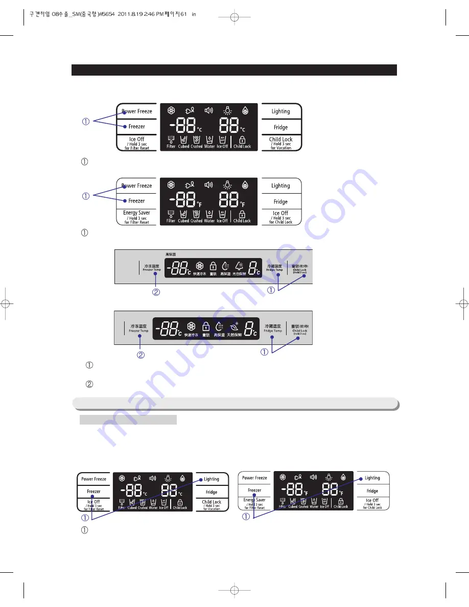
How to Enter Exhibition/Cooling-Off Mode
61
Press the Power Freeze and the Freezer buttons for 3 seconds at the same time.
Press the Freezer and the Lighting buttons for 12 seconds at the same time.
Press the Power Freeze and the Freezer buttons for 8 seconds at the same time.
RSG5K/F/D*
RSG257*
●
At the normal operation mode, press the Freezer and the Lighting buttons for 12 seconds at the same
time. Then, the Display Panel will be shifted to the Option Setting mode.
4-1-8) Option Setting Function
RSG5/K/F/D*, RSG257*
RSG5/K/F/D*
RSG257*
How to Enter Option Setting mode
When the Display Panel blinks for 4 seconds at an interval of 0.5 second pressing the
Fridge temp and the Child Lock buttons for 6 seconds at the same time.
Take your finger off from all the button and press the Freezer temp button.
RSG5V*
RSG5B*
Summary of Contents for RSG5D series
Page 2: ......
Page 11: ...11 PRODUCT SPECIFICATIONS Comparison with competitor...
Page 12: ...2 3 1 Basic Specification PRODUCT SPECIFICATIONS 2 3 2 Electric Parts Specification 12...
Page 13: ...PRODUCT SPECIFICATIONS 13 AC 250V 3A AC 125V 6A AC 125V 6A AC 250V 3A...
Page 72: ...TROUBLE SHOOTING SPM FREEWHEELING DIODE Voltage 72...
Page 90: ...90 PCB DIAGRAM 5 3 Connector Arrangement Description Main Board...
Page 91: ...91 PCB DIAGRAM 5 4 LED blinking frequency depending on protecting functions...
Page 92: ...92 6 WIRING DIAGRAM 6 1 RSG5D F K 220 240V...
Page 93: ...93 93 WIRING DIAGRAM 6 2 RSG5D F K 220 240V...
Page 94: ...94 WIRING DIAGRAM 6 3 RSG5K F D 110 127V...
Page 95: ...95 WIRING DIAGRAM 6 4 RSG257...
Page 96: ...96 WIRING DIAGRAM 6 5 RSG5B V...
Page 97: ...97 97 7 SCHEMATIC DIAGRAM BLOCK DIAGRAM 7 1 Main PCB Schematic Diagram...
Page 98: ...98 98 98 SCHEMATIC DIAGRAM BLOCK DIAGRAM 7 2 Main PCB Schematic Diagram...
Page 99: ...99 99 SCHEMATIC DIAGRAM BLOCK DIAGRAM 7 2 1 BLOCK DIAGRAM RSG5F D...
Page 100: ...100 100 100 SCHEMATIC DIAGRAM BLOCK DIAGRAM 7 2 2 BLOCK DIAGRAM RSG5K...
Page 101: ...101 101 101 SCHEMATIC DIAGRAM BLOCK DIAGRAM 7 2 3 BLOCK DIAGRAM RSG257...
Page 102: ...102 102 102 SCHEMATIC DIAGRAM BLOCK DIAGRAM 7 2 4 BLOCK DIAGRAM RSG5B V...
Page 103: ...103 103 103 SCHEMATIC DIAGRAM BLOCK DIAGRAM 7 2 5 BLOCK DIAGRAM RSG257...
Page 104: ...104 104 104 SCHEMATIC DIAGRAM BLOCK DIAGRAM 7 2 6 BLOCK DIAGRAM RSG257...
Page 105: ...105 105 105 SCHEMATIC DIAGRAM BLOCK DIAGRAM 7 2 7 BLOCK DIAGRAM Inverter PBA...
Page 106: ...106 8 REFERENCE INFORMATION 8 1 RSG5...


