87
If Failure Condition is detected during compressor is operating, immediately stop Compressor operating and stand
by 5 minutes. During this 5 minutes, RPM command signal is not available. It means, even if available RPM
command signal is applied to the compressor, it does not work and keep standing by.
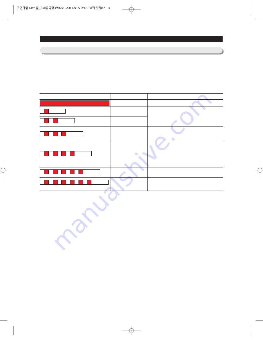
Blinking time is 1 second and dwell time is 2 seconds.
LED blinking frequency depending on protecting functions
If the same blinking, After 5 minutes, Follow the Remarks
TROUBLESHOOTING
4-2-19) LED blinking frequency depending on protecting functions
LED Blinking Frequency
Protecting Functions
Normal Operation
Starting Failure
SPM Fault
Abnormal Current
Detection
Motor Locked/Over RPM
Under Voltage
Over Voltage
Remarks
N/A
1. Short between COMP U, V, and W phase(CN04)
2. Short among IPM Pins(No. #1~26)
3. Drop the IPM operating Voltage under DC 13.5V
4. Other cases, check the COMP, cycle, etc.
1. Open the COMP wire(CN04)
2. Bad condition of R1(ex. Bad soldering.)
3. Other cases, check the COMP, cycle, etc.
1. Operating the locked rotor COMP within 5 second.
2. Operating the COMP under 1000 RPM more than 5
second.
3. Short the shunt resistor(R1) between leads.
4. Occur the huge change of input voltage in a momeent
5. Other cases, check the COMP, cycle, etc.
1. Drop the input voltage under AC 106V
2. Short resistor R312(DC link resistor)
1. Increase the input voltage over AC 310V
2. Short resistor among R309, R310 and R311(DC link
resistor)
Summary of Contents for RSG5D series
Page 2: ......
Page 11: ...11 PRODUCT SPECIFICATIONS Comparison with competitor...
Page 12: ...2 3 1 Basic Specification PRODUCT SPECIFICATIONS 2 3 2 Electric Parts Specification 12...
Page 13: ...PRODUCT SPECIFICATIONS 13 AC 250V 3A AC 125V 6A AC 125V 6A AC 250V 3A...
Page 72: ...TROUBLE SHOOTING SPM FREEWHEELING DIODE Voltage 72...
Page 90: ...90 PCB DIAGRAM 5 3 Connector Arrangement Description Main Board...
Page 91: ...91 PCB DIAGRAM 5 4 LED blinking frequency depending on protecting functions...
Page 92: ...92 6 WIRING DIAGRAM 6 1 RSG5D F K 220 240V...
Page 93: ...93 93 WIRING DIAGRAM 6 2 RSG5D F K 220 240V...
Page 94: ...94 WIRING DIAGRAM 6 3 RSG5K F D 110 127V...
Page 95: ...95 WIRING DIAGRAM 6 4 RSG257...
Page 96: ...96 WIRING DIAGRAM 6 5 RSG5B V...
Page 97: ...97 97 7 SCHEMATIC DIAGRAM BLOCK DIAGRAM 7 1 Main PCB Schematic Diagram...
Page 98: ...98 98 98 SCHEMATIC DIAGRAM BLOCK DIAGRAM 7 2 Main PCB Schematic Diagram...
Page 99: ...99 99 SCHEMATIC DIAGRAM BLOCK DIAGRAM 7 2 1 BLOCK DIAGRAM RSG5F D...
Page 100: ...100 100 100 SCHEMATIC DIAGRAM BLOCK DIAGRAM 7 2 2 BLOCK DIAGRAM RSG5K...
Page 101: ...101 101 101 SCHEMATIC DIAGRAM BLOCK DIAGRAM 7 2 3 BLOCK DIAGRAM RSG257...
Page 102: ...102 102 102 SCHEMATIC DIAGRAM BLOCK DIAGRAM 7 2 4 BLOCK DIAGRAM RSG5B V...
Page 103: ...103 103 103 SCHEMATIC DIAGRAM BLOCK DIAGRAM 7 2 5 BLOCK DIAGRAM RSG257...
Page 104: ...104 104 104 SCHEMATIC DIAGRAM BLOCK DIAGRAM 7 2 6 BLOCK DIAGRAM RSG257...
Page 105: ...105 105 105 SCHEMATIC DIAGRAM BLOCK DIAGRAM 7 2 7 BLOCK DIAGRAM Inverter PBA...
Page 106: ...106 8 REFERENCE INFORMATION 8 1 RSG5...


