


SBS TYPE
BASIC : RSH1DTMH
MODEL NAME (MODEL CODE) :
RSJ1Z/K***
RS21H*L**
RSJ1Y/J***
RS21H****
RSJ1P/F***
RS23H****
REFRIGERATOR
REFRIGERATOR
CONTENTS
- For the latest parts information, Please access to our service web site
(• North America : http;//service.samsungportal.com • Latin America : http;//latin.samsungportal.com
• CIS : http;//cis.samsungportal.com • Europe : http;//europe.samsungportal.com
• China : http;//china.samsungportal.com • Asia : http;//asia.samsungportal.com
• Mideast & Africa : http;//mea.samsungportal.com)
RS21H*L**
RS21/23H****
RSJ1****
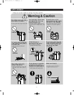
PRECAUTIONS(SAFETY WARNINGS)
5
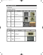
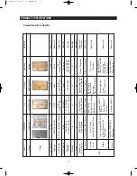
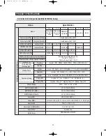
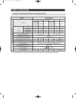
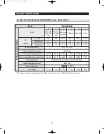
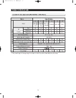
PRODUCT SPECIFICATIONS
8
DISASSEMBLY & REASSEMBLY
21
TROUBLE SHOOTING
48
PCB DIAGRAM
78
WIRING DIAGRAM
82
SCHEMATIC DIAGRAM
94
REFERENCE INFORMATION
100
Summary of Contents for RSJ1K Series
Page 2: ......
Page 68: ...TROUBLE SHOOTING SPM FREEWHEELING DIODE Voltage 68...
Page 82: ...82 6 WIRING DIAGRAM 6 1 RS21 23H Series CHINA Z Option Inverter COMP...
Page 83: ...83 WIRING DIAGRAM 6 2 RS21 23H Series CHINA V S Option Inverter COMP...
Page 84: ...84 WIRING DIAGRAM 6 3 RS21 23H Series Z Y Option Inverter COMP...
Page 85: ...85 WIRING DIAGRAM 6 4 RS21 23H Series P U Option Inverter COMP...
Page 86: ...86 WIRING DIAGRAM 6 5 RS21 23H Series V S Option Inverter COMP...
Page 87: ...87 WIRING DIAGRAM 6 6 RS21 23H Series K J Option AC COMP...
Page 88: ...88 WIRING DIAGRAM 6 7 RS21 23H Series F D Option AC COMP...
Page 89: ...89 WIRING DIAGRAM 6 8 RS21 23H Series B N Option AC COMP...
Page 90: ...90 WIRING DIAGRAM 6 9 RSJ1 Series Z Option Inverter COMP...
Page 91: ...91 WIRING DIAGRAM 6 10 RSJ1 Series P Option Inverter COMP...
Page 92: ...92 WIRING DIAGRAM 6 11 RSJ1 Series K J Option AC COMP...
Page 93: ...93 WIRING DIAGRAM 6 12 RSJ1 Series F D Option AC COMP...
Page 94: ...94 94 7 SCHEMATIC DIAGRAM 7 1 Main PCB Schematic Diagram RSJ1 Series...
Page 95: ...95 95 SCHEMATIC DIAGRAM 7 2 Main PCB Schematic Diagram RS21 23H Series...
Page 96: ...96 SCHEMATIC DIAGRAM 7 3 Inverter PCB Schematic Diagram RSJ1 RS21 23H Series...
Page 97: ...97 SCHEMATIC DIAGRAM 7 3 1 BLOCK DIAGRAM RS21 23H Series All...
Page 98: ...98 SCHEMATIC DIAGRAM 7 3 2 BLOCK DIAGRAM RS21 23H Series Inverter COMP...
Page 99: ...99 SCHEMATIC DIAGRAM 7 3 3 BLOCK DIAGRAM RS21 23H Series AC COMP...
Page 100: ...8 REFERENCE INFORMATION Label Location 8 1 RSJ1 Series Nomenclature 100...
Page 101: ...101 REFERENCE INFORMATION Label Location 8 2 RS21 23H Series Nomenclature...
Page 106: ...106 REFERENCE INFORMATION 8 6 Air Circulation...


