I/O PORTS
S3C80A5B
9-4
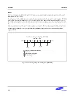
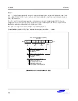
Port 0 Control Register, Low Byte (P0CONL)
E9H, Set 1, R/W
.7
.6
.5
.4
.3
.2
.1
.0
MSB
LSB
P0.3/INT3
P0.0/INT0
P0.2/INT2
P0.1/INT1
P0CONL Pin Configureation Settings:
00
01
10
11
Input mode; interrupt on falling edges
Input mode; interrupt on rising and falling edges
Push-pull output mode
Input mode; interrupt on rising edges
Figure 9-3. Port 0 Low-Byte Control Register (P0CONL)
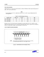
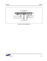
PORT 0 INTERRUPT ENABLE REGISTER (P0INT)
The port 0 interrupt control register, P0INT, is used to enable and disable external interrupt input at individual P0 pins
(see Figure 10-5). To enable a specific external interrupt, you set its P0INT.n bit to "1". You must also be sure to
make the correct settings in the corresponding port 0 control register (P0CONH, P0CONL).
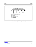
PORT 0 INTERRUPT PENDING REGISTER (P0PND)
The port 0 interrupt pending register, P0PND, contains pending bits (flags) for each port 0 interrupt (see Figure 10-6).
When a P0 external interrupt is acknowledged by the CPU, the service routine must clear the pending condition by
writing a "0" to the appropriate pending flag in the P0PND register (Writing a "1" to the pending bit has no effect).
NOTE
A hardware reset(INTR, POR) clears the P0INT and P0PND registers to '00H'. For this reason, the
application program's initialization routine must enable the required external interrupts for port 0, and for the
other I/O ports.


