S3C80A5B
BASIC TIMER AND TIMER 0
10-3
BASIC TIMER FUNCTION DESCRIPTION
Watchdog Timer Function
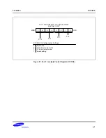
You can program the basic timer overflow signal (BTOVF) to generate a reset by enabling the watchdog function. A
reset clears BTCON to '00H', automatically enabling the watchdog timer function. A reset also selects the CPU
clock (as determined by the current CLKCON register setting),divided by 4096, as the BT clock.
A reset whenever a basic timer counter overflow occurs. During normal operation, the application program must
prevent the overflow, and the accompanying reset operation, from occurring. To do this, the BTCNT value must be
cleared (by writing a "1" to BTCON.1) at regular intervals.
If a system malfunction occurs due to circuit noise or some other error condition, the BT counter clear operation will
not be executed and a basic timer overflow will occur, initiating a reset. In other words, during normal operation, the
basic timer overflow loop (a bit 7 overflow of the 8-bit basic timer counter, BTCNT) is always broken by a BTCNT
clear instruction. If a malfunction does occur, a reset is triggered automatically.
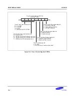
TIMER 0 CONTROL REGISTER (T0CON)
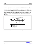
You use the timer 0 control register, T0CON, to
— Select the timer 0 operating mode (interval timer)
— Select the timer 0 input clock frequency
— Clear the timer 0 counter, T0CNT
— Enable the timer 0 overflow interrupt or timer 0 match interrupt
— Clear timer 0 match interrupt pending conditions
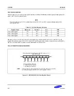
T0CON is located in set 1, at address D2H, and is read/write addressable using Register addressing mode.
A reset clears T0CON to '00H'. This sets timer 0 to normal interval timer mode, selects an input clock frequency of
f
OSC
/4096, and disables all timer 0 interrupts. You can clear the timer 0 counter at any time during normal operation
by writing a "1" to T0CON.3.
The timer 0 overflow interrupt (T0OVF) is interrupt level IRQ0 and has the vector address FAH. When a timer 0
overflow interrupt occurs and is serviced by the CPU, the pending condition is cleared automatically by hardware.
To enable the timer 0 match interrupt (IRQ0, vector FCH), you must write T0CON.1 to "1". To detect a match
interrupt pending condition, the application program polls T0CON.0. When a "1" is detected, a timer 0 match
interrupt is pending. When the interrupt request has been serviced, the pending condition must be cleared by
software by writing a "0" to the timer 0 interrupt pending bit, T0CON.0.

