background image

69

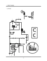
Ⅴ. CIRCUIT DIAGRAM

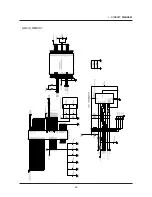
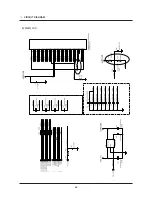
9) MAIN_POWER

Summary of Contents for S85 - Digital Camera - Compact

Page 1: ......

Page 2: ...IEW AND PARTS LIST 1 MAIN ASSEMBLY 14 2 FRAME ASSEMBLY 16 3 BARREL ASSEMBLY 20 4 FRONT COVER ASSEMBLY 24 5 MIDDLE COVER ASSEMBLY 26 6 BACK COVER ASSEMBLY 28 7 PACKING ITEM 30 ADJUSTMENT 1 FIRMWARE 34...

Page 3: ...OACH9S VOLATGE UI 62 3 MAIN_MEMORY 63 4 MAIN_USB IF 64 5 MAIN_LENS DRIVER 65 6 MAIN_LCD 66 7 MAIN_SYSTEM BLOCK 67 8 MAIN_POWER BLOCK 68 9 MAIN_POWER 69 10 MAIN_AD9920 70 11 CCD 71 12 CCD Pin Define 72...

Page 4: ...ognition AE Metering Multi Spot Center weighted Compensation 2EV 1 3EV steps ISO Equivalent Auto 50 100 200 400 800 1600 Flash Modes Auto Auto Red eye reduction Fill in flash Slow sync Flash off Red e...

Page 5: ...e Capture Storage Media Internal memory About 19MB flash memory External Memory Optional MMC card Up to 1GB guaranteed SD card Up to 2GB guaranteed SDHC card Up to 4GB guaranteed Internal Memory capac...

Page 6: ...ils Slide show Movie Clip Interface Digital output connector USB 2 0 Audio Mono Video output NTSC PAL user selectable DC Adapter 3 3V Power Source Primary Battery 2 X AA Alkaline Rechargeable battery...

Page 7: ...cessor better than Pentium II 450MHz Pentium 800MHz recommended Minimum 128MB RAM Over 512MB recommended 200MB of available hard disk space Over 1GB recommend 1024x768 pixels 16bit color display compa...

Page 8: ...3 LCD monitor indicator 8 SPECIFICATION Recording mode Image Full Status...

Page 9: ...ital Zoom rate 6 Battery 7 Image Size 8 Image Quality Frame Rate 9 Metering 10 Drive mode 11 ISO 12 White Balance 13 Exposure compensation 14 Date Time 2007 08 01 01 00 PM 15 Camera shake Warning 16 A...

Page 10: ...mode 2 Memory card indicator 3 Folder name File name 100 0010 4 Battery 5 ISO 50 1600 6 Aperture value F2 8 F4 6 7 Shutter speed 15 1 2000 8 Flash ON OFF 9 Image size 3264X2448 320X240 10 Recording d...

Page 11: ...11 SPECIFICATION 4 4 C CO ON NN NE EC CT TI IO ON N D DI IA AG GR RA AM M Card Reader SD Card USB Cable AV Cable TV Monitor IBM MAC Lap top AC Adaptor...

Page 12: ...n Speaker Microphone Lens Lens cover Flash Self timer lamp AF sensor USB AV connection terminal DC input connection port LCD monitor 5 function button E Effects button Play mode Printer button Fn Dele...

Page 13: ...ION Battery chamber Battery chamber cover Tripod socket Memory card slot Information Up button Flash Left button MENU OK button Self timer Right button Macro Down button Play Pause button Bottom 5 Fun...

Page 14: ...EXPLODED VIEW AND PART LIST 14 1 3 1 2 1 3 1 2 1 1 1 4 1 MAIN ASSEMBLY...

Page 15: ...ART LIST 2 9 2 11 2 12 2 6 2 27 2 29 2 32 2 28 2 26 2 3 2 2 2 4 2 7 2 8 2 25 2 15 2 23 2 18 2 23 2 19 2 21 2 20 2 16 2 15 2 14 2 10 2 39 2 40 2 36 2 38 2 37 2 22 2 13 2 24 2 34 2 35 2 1 2 30 2 31 2 33...

Page 16: ...50 3 52 3 51 3 52 3 32 3 33 3 34 3 35 3 36 3 34 3 37 3 34 3 4 3 34 4 40 4 40 4 40 3 41 3 42 3 43 3 58 3 61 3 57 3 54 3 38 3 55 3 56 4 50 4 59 3 44 3 19 3 21 3 60 3 62 3 63 3 64 3 4 3 4 3 6 3 5 3 8 3...

Page 17: ...24 EXPLODED VIEW AND PART LIST 4 FRONT COVER ASSEMBLY 4 1 4 4 4 5 4 2 4 3 4 6 4 7 4 8...

Page 18: ...26 EXPLODED VIEW AND PART LIST 5 10 5 16 5 3 5 2 5 13 5 11 5 14 5 15 5 18 5 7 5 6 5 5 5 4 5 1 5 17 5 12 5 9 5 8 5 MIDDLE COVER ASSEMBLY...

Page 19: ...28 EXPLODED VIEW AND PART LIST 6 1 6 3 6 2 6 4 6 9 6 8 6 7 6 10 6 5 6 6 6 11 6 BACK COVER ASSEMBLY...

Page 20: ...30 EXPLODED VIEW AND PART LIST 7 PACKING ITEM 7 8 7 15 8 18 7 16 7 1 7 12 7 11 7 17 7 7 7 5 7 6 7 19 7 14 7 2 7 9 7 10 7 3 7 13...

Page 21: ...7A MAIN_PCB_ASSY 1 O 2 14 Q8100099101A AD81 06357A MAIN_BD_ABSORBER_FRONT 1 X 2 15 Q6002026301A AD81 01116A SCREW 4 X 2 16 Q8100099201A AD81 06358A MAIN_BD_DOUBLE_TAPE 1 X 2 17 Q8100099301A AD81 06359...

Page 22: ...8 Q7411130201A AD66 00549A ZOOM GEAR D 1 X 3 9 Q7212195001A AD81 03666A ZOOM GEAR A 1 X 3 10 Q7411125501A AD66 00543A ZOOM GEAR SHAFT 2 X 3 11 Q9611142007 6001 002171 SCREW M1 4 X L2 0 2 X 3 12 Q72122...

Page 23: ...2 X L2 5 1 X 3 46 Q7212205102A AD64 01839A FRONT PANEL 1 X 3 47 Q7212205302A AD63 01521A BARRIER B 2 X 3 48 Q7212205202A AD63 01520A BARRIER A 2 X 3 49 6107075901A DNA BARRIER CLOSE SPRING 2 X 3 50 Q7...

Page 24: ...05591A SPEAKER_NONWOVEN 1 X 5 4 Q8100096401A AD81 06330A SHUTTER_BUTTON_SPRING 1 O 5 5 Q8100096501A AD81 06331A SHUTTER_BUTTON 1 O 5 6 Q8100016201A AD81 05527A MODE_DIAL_SPRING 1 O 5 7 Q8100096601A AD...

Page 25: ...4_WAY_BUTTON 1 X 6 6 Q8100101501A AD81 06381A OK_BUTTON 1 X 6 7 Q8100101601A AD81 06382A T W_BUTTON_SILVER 1 X 6 8 Q8100101701A AD81 06383A SPRING_T W_BUTTON 1 X 6 9 Q8100101801A AD81 06384A T W_BUTT...

Page 26: ...1660 SERVICE_CENTER_TURKEY 1 O Q6901279601A DNA GT_BOX_KENOX_S85_KOR_Silver 1 X Q6901279701A DNA GT_BOX_Samsung_S85_EXP_AUS_SL 1 X Q6901279801A DNA GT_BOX_Samsung_S85_USA_SL 1 X Q6901291801A AD69 0137...

Page 27: ...01A AD81 00700A AC CODE CABLE_CHI D1 1 O Q3801003401B 3903 000349 AC CODE CABLE_AUS D1 1 O 7 18 Q4301001801A AD81 00867A ALKALINE 1 5V AA 2EA DURACEL ULTRA 1 O Q6809006602A AD68 02008A U_MANUAL_ROHS_C...

Page 28: ...onnect the AC adapter or a fully charged battery 3 Turn the camera off 4 Press and hold the PLAY button for approximately 2 seconds while holding down the TELE button and the OK button simultaneously...

Page 29: ...e data onto your PC before updating the firmware The file name must be s385n elf Copy the file to the root directory of the SD card 2 Connect the AC adapter or a fully charged battery To upgrade the f...

Page 30: ...grade is progressed and the Status LED Green of the camera blinks during upgrade When the upgrade is complete the Power button LED is automatically turned off 6 Turn the camera on again and run RESET...

Page 31: ...Procedures for Each Feature 1 Reading EEPROM You can read data from the EEPROM according to the procedures below Requirements Special Cable USB EEPROM TOOL Program Test Mode Recognition Driver Camera...

Page 32: ...MODE item using the Right direction button 1 Remove the memory card from the camera 2 Connect the AC adapter or a fully charged battery 3 Turn the camera off 4 Press and hold the PLAY button for appro...

Page 33: ...39 ADJUSTMENT Press the MENU button to show the sub menu of the USB MODE Select OK for the USB MODE using the Left direction button and then press the MENU button...

Page 34: ...40 ADJUSTMENT The MS to PC Mode message appears on the LCD screen of the camera 6 Connect the camera with the PC using the Adjustment Jack Board when the camera is in the MS to PC Mode...

Page 35: ...ra USB MODE Disable to the PC for the first time make the camera recognized according to the procedures below After that the camera will automatically be recognized by the PC when you connect the came...

Page 36: ...TMENT To confirm that the camera is properly recognized check if the camera is registered as an Imaging Device in the Control Panel Device Manager window When the camera is recognized click the Finish...

Page 37: ...uncompress the EEPROM TOOL program Installation is not necessary 8 Run the EEPROM TOOL program 9 If you click the Read From Camera from the EEPROM TOOL program menu EEPROM data is loaded and the OK m...

Page 38: ...44 ADJUSTMENT 10 Click the Write File from the EEPROM TOOL program menu to save the EEPROM data into a desired folder...

Page 39: ...Caution Make sure to set USB MODE to normal so that USB MODE is marked as OK as shown by the figure below before shipping the product Normal State USB MODE is marked as OK Abnormal State USB MODE is...

Page 40: ...ting onto EEPROM You can write data onto the EEPROM according to the procedures below Requirements Specal Cable USB EEPROM TOOL Program Test Mode Recognition Driver Camera onto which standard EEPROM d...

Page 41: ...y charged battery 3 Turn the camera off 4 Press and hold the PLAY button for approximately 2 seconds while holding down the TELE button and the MENU button simultaneously 5 Set the USB MODE to NG acco...

Page 42: ...48 ADJUSTMENT Press the MENU button to show the sub menu of the USB MODE Select OK for the USB MODE using the Left direction button and then press the MENU button...

Page 43: ...49 ADJUSTMENT The MS to PC Mode message appears on the LCD screen of the camera 6 Connect the camera with the PC using the Adjustment Jack Board when the camera is in the MS to PC Mode...

Page 44: ...ra USB MODE Disable to the PC for the first time make the camera recognized according to the procedures below After that the camera will automatically be recognized by the PC when you connect the came...

Page 45: ...TMENT To confirm that the camera is properly recognized check if the camera is registered as an Imaging Device in the Control Panel Device Manager window When the camera is recognized click the Finish...

Page 46: ...52 ADJUSTMENT 7 Download and uncompress the EEPROM TOOL program Installation is not necessary 8 If you click the Read File from the EEPROM TOOL program menu and open a standard EEPROM data...

Page 47: ...53 ADJUSTMENT 9 If you click the Write To Camera from the EEPROM TOOL program menu the EEPROM data is written onto the camera and the OK message appears at the bottom after a moment...

Page 48: ...Caution Make sure to set USB MODE to normal so that USB MODE is marked as OK as shown by the figure below before shipping the product Normal State USB MODE is marked as OK Abnormal State USB MODE is...

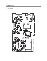
Page 49: ...55 PATTERN DIAGRAM 1 PARTS ARRANGEMENT FOR EACH PCB ASS Y 1 MAIN_TOP...

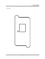
Page 50: ...56 PATTERN DIAGRAM 2 MAIN_BOTTOM...

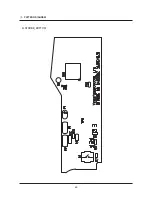
Page 51: ...57 PATTERN DIAGRAM 3 CCD_TOP...

Page 52: ...58 PATTERN DIAGRAM 4 CCD_BOTTOM...

Page 53: ...59 PATTERN DIAGRAM 5 STROBE_TOP...

Page 54: ...60 PATTERN DIAGRAM 6 STROBE_BOTTOM...

Page 55: ...61 CIRCUIT DIAGRAM 1 MAIN_COACH9S GPIO...

Page 56: ...62 CIRCUIT DIAGRAM 2 MAIN_COACH9S VOLATGE UI...

Page 57: ...63 CIRCUIT DIAGRAM 3 MAIN_MEMORY...

Page 58: ...64 CIRCUIT DIAGRAM 4 MAIN_USB IF...

Page 59: ...65 CIRCUIT DIAGRAM 5 MAIN_LENS DRIVER...

Page 60: ...66 CIRCUIT DIAGRAM 6 MAIN_LCD...

Page 61: ...67 CIRCUIT DIAGRAM 7 MAIN_SYSTEM BLOCK...

Page 62: ...68 CIRCUIT DIAGRAM 8 MAIN_POWER BLOCK...

Page 63: ...69 CIRCUIT DIAGRAM 9 MAIN_POWER...

Page 64: ...70 CIRCUIT DIAGRAM 10 MAIN_AD9920...

Page 65: ...71 CIRCUIT DIAGRAM 11 CCD...

Page 66: ...72 CIRCUIT DIAGRAM 12 CCD Pin Define...

Page 67: ...73 CIRCUIT DIAGRAM 13 MODE DIAL...

Page 68: ...74 CIRCUIT DIAGRAM 14 STROBE...

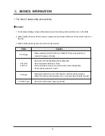
Page 69: ...n Parts Caution F PCB type CCD CCD IR CUT PCB type CONTACT type When assembling the F PCB to the CONNECTOR by using pincette be careful of tearing and hooking Be careful of the handprinting while hand...

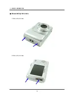
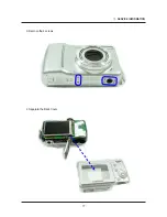
Page 70: ...76 SERVICE INFORMATION Disassembling the Camera 1 Remove the 2 screws 2 Remove the 2 screws...

Page 71: ...77 SERVICE INFORMATION 3 Remove the 4 screws 4 Separate the Back Cover...

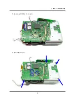
Page 72: ...78 SERVICE INFORMATION 5 Separate the PCB from the connector 6 Remove the 3 screws from the inside of the Front Cover...

Page 73: ...79 SERVICE INFORMATION 7 Separate the Front Cover 8 Detach the sticker at the microphone part...

Page 74: ...80 SERVICE INFORMATION 9 Remove the 2 screws 10 Separate the PCB from the connector...

Page 75: ...81 SERVICE INFORMATION 11 Separate the LCD Assy 12 Unsolder the contact points of the Top PCB and unsolder 2 wires from the PCB...

Page 76: ...82 SERVICE INFORMATION 13 Remove the 2 screws 14 Unsolder the battery terminals...

Page 77: ...83 SERVICE INFORMATION 15 Separate the PCB from the connector 16 Remove the 4 screws...

Page 78: ...84 SERVICE INFORMATION 17 Separate the Main PCB Bottom of the Main PCB CCD is installed...

Page 79: ...85 SERVICE INFORMATION Main PCB 18 Remove the 2 screws...

Page 80: ...86 SERVICE INFORMATION 19 Separate the Flash PCB 20 Remove the 3 screws...

Page 81: ...87 SERVICE INFORMATION 21 Separate the barrel Assy...

Page 82: ...88 SERVICE INFORMATION Disassembling the Barrel 1 Unsolder the wires from Shutter PCB and remove the 3 screws 2 Separate the Lens Base Assy...

Page 83: ...89 SERVICE INFORMATION 3 Remove the fixing pin from the Shutter PCB 4 Remove the fixing pin from the Shutter PCB...

Page 84: ...SERVICE INFORMATION 5 Separate the Outer Guide Barrel with reference to the part circled in red as shown below 6 Separate the Outer Guide Barrel with reference to the part circled in red as shown bel...

Page 85: ...91 SERVICE INFORMATION 7 Separate the Outer Guide Barrel 8 Separate the Inner Cam Barrel Assy with reference to the part circled in red as shown below...

Page 86: ...92 SERVICE INFORMATION 9 Separate the Inner Cam Barrel Assy 10 Separate the Lens Cap Assy with reference to the part circled in red as shown below...

Page 87: ...93 SERVICE INFORMATION 11 Separate the Lens Cap Assy Check the reference point circled in blue for reassembly 12 Separate the Shutter Assy with reference to the part circled in red as shown below...

Page 88: ...94 SERVICE INFORMATION 13 Separate the Shutter Assy 14 Separate the Front Lens Group Assy with reference to the part circled in red as shown below...

Page 89: ...95 SERVICE INFORMATION 15 Separate the Front Lens Group Assy 16 Separate the Guide Plate as shown below...

Page 90: ...96 SERVICE INFORMATION 17 Separate the Guide Plate Reference for Assembly Check the reference point circled in red for the assembly...

Page 91: ...rence for Assembly Check the point circled in red in relation to the Shutter PCB position for reassembly Reference for Assembly Check the position of the photo interrupter in relation to the Shutter P...

Page 92: ...98 SERVICE INFORMATION Reference for Assembly Check the position of the photo interrupter in relation to the Shutter PCB position for reassembly...

Reviews: