No.
Description
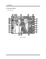
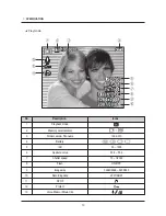
Icons
1
Recording mode
2
Memory card icon / Internal memory icon
3
Number of available shots remaining
6
Remaining time
00:00:00
4
Voice Memo
5
Optical / Digital Zoom bar /
Digital Zoom rate
6
Battery
7
Image Size
8
Image Quality / Frame Rate
9
Metering
10
Drive mode
11
ISO
12
White Balance
13
Exposure compensation
14
Date / Time
2007/08/01 01:00 PM
15
Camera shake Warning
16
Auto Focus Frame
17
Sharpness / Without Sound
18
Contrast
19
Macro
20
Self-timer
21
Flash
22
Face Recognition
23
Aperture Value / Shutter Speed
F2.8, 1/30
24
Color / Saturation
9
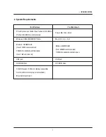
Ⅰ. SPECIFICATION
/
Summary of Contents for S85 - Digital Camera - Compact
Page 1: ......
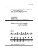
Page 8: ...3 LCD monitor indicator 8 SPECIFICATION Recording mode Image Full Status...
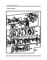
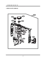
Page 14: ...EXPLODED VIEW AND PART LIST 14 1 3 1 2 1 3 1 2 1 1 1 4 1 MAIN ASSEMBLY...
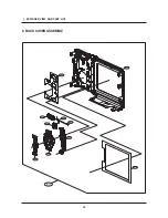
Page 17: ...24 EXPLODED VIEW AND PART LIST 4 FRONT COVER ASSEMBLY 4 1 4 4 4 5 4 2 4 3 4 6 4 7 4 8...
Page 49: ...55 PATTERN DIAGRAM 1 PARTS ARRANGEMENT FOR EACH PCB ASS Y 1 MAIN_TOP...
Page 50: ...56 PATTERN DIAGRAM 2 MAIN_BOTTOM...
Page 51: ...57 PATTERN DIAGRAM 3 CCD_TOP...
Page 52: ...58 PATTERN DIAGRAM 4 CCD_BOTTOM...
Page 53: ...59 PATTERN DIAGRAM 5 STROBE_TOP...
Page 54: ...60 PATTERN DIAGRAM 6 STROBE_BOTTOM...
Page 55: ...61 CIRCUIT DIAGRAM 1 MAIN_COACH9S GPIO...
Page 56: ...62 CIRCUIT DIAGRAM 2 MAIN_COACH9S VOLATGE UI...
Page 57: ...63 CIRCUIT DIAGRAM 3 MAIN_MEMORY...
Page 58: ...64 CIRCUIT DIAGRAM 4 MAIN_USB IF...
Page 59: ...65 CIRCUIT DIAGRAM 5 MAIN_LENS DRIVER...
Page 60: ...66 CIRCUIT DIAGRAM 6 MAIN_LCD...
Page 61: ...67 CIRCUIT DIAGRAM 7 MAIN_SYSTEM BLOCK...
Page 62: ...68 CIRCUIT DIAGRAM 8 MAIN_POWER BLOCK...
Page 63: ...69 CIRCUIT DIAGRAM 9 MAIN_POWER...
Page 64: ...70 CIRCUIT DIAGRAM 10 MAIN_AD9920...
Page 65: ...71 CIRCUIT DIAGRAM 11 CCD...
Page 66: ...72 CIRCUIT DIAGRAM 12 CCD Pin Define...
Page 67: ...73 CIRCUIT DIAGRAM 13 MODE DIAL...
Page 68: ...74 CIRCUIT DIAGRAM 14 STROBE...
Page 70: ...76 SERVICE INFORMATION Disassembling the Camera 1 Remove the 2 screws 2 Remove the 2 screws...
Page 71: ...77 SERVICE INFORMATION 3 Remove the 4 screws 4 Separate the Back Cover...
Page 73: ...79 SERVICE INFORMATION 7 Separate the Front Cover 8 Detach the sticker at the microphone part...
Page 74: ...80 SERVICE INFORMATION 9 Remove the 2 screws 10 Separate the PCB from the connector...
Page 76: ...82 SERVICE INFORMATION 13 Remove the 2 screws 14 Unsolder the battery terminals...
Page 77: ...83 SERVICE INFORMATION 15 Separate the PCB from the connector 16 Remove the 4 screws...
Page 78: ...84 SERVICE INFORMATION 17 Separate the Main PCB Bottom of the Main PCB CCD is installed...
Page 79: ...85 SERVICE INFORMATION Main PCB 18 Remove the 2 screws...
Page 80: ...86 SERVICE INFORMATION 19 Separate the Flash PCB 20 Remove the 3 screws...
Page 81: ...87 SERVICE INFORMATION 21 Separate the barrel Assy...

