Samsung Electronics
2-2
Adjustment
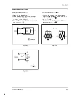
Fig. 2-3
Carry out the following periodic maintenance
checks
in order not only to fully exhibit the functions and
operate the set, but also for the equipment and
tape.
After repairing, service the set as follows :
2-3-1 Cleaning of Drum Assembly
1. Gently apply lens tissue soaked in ethyl alcohol
to the Drum assembly.
Clean the Upper Drum assembly while rotating
it slowly counterclockwise (by hand).
2-3-2 Cleaning of Tape Path
1. In EJECT mode, clean the tape path system (from
Pole Tension P1 through Pole Review P7, Pinch
Roller and Capstan Shaft) and the Lower Drum.
Using the lens tissue soaked in ethyl alcohol.
Note :
Do not rotate the motor by power or
rotate the Upper Drum assembly clockwise.
Also, the Head tip will be damaged if the lens
tissue is moved in a perpendicular direction.
Be sure to follow these instructions when
cleaning the Drum Ass’y.
Note :
Make sure that no oil or grease adheres
to the lens tissue.
P3
P1
P2
P6
P4
P7
PINCH
ROLLER
P5
2-3 Maintenance
Summary of Contents for SC-L710
Page 61: ...Samsung Electronics 4 44 Alignment and Adjustment MEMO MEMO ...
Page 63: ...Samsung Electronics 5 2 Exploded View and Parts List 5 1 Mechanical Parts 1 600 ...
Page 65: ...Samsung Electronics 5 4 Exploded View and Parts List 5 2 Mechanical Parts 2 ...
Page 67: ...Samsung Electronics 5 6 Exploded View and Parts List 5 3 Mechanical Parts 3 601 ...
Page 69: ...Samsung Electronics 5 8 Exploded View and Parts List 5 4 Ass y EVF 262 269 904 271 300 ...
Page 71: ...Samsung Electronics 5 10 Exploded View and Parts List 5 5 Ass y Right ...
Page 73: ...Samsung Electronics 5 12 Exploded View and Parts List 5 6 Ass y LCD ...
Page 75: ...Samsung Electronics 5 14 Exploded View and Parts List 5 7 Ass y Left ...
Page 77: ...Samsung Electronics 5 16 Exploded View and Parts List 5 9 Ass y Front ...
Page 79: ...Samsung Electronics 5 18 Exploded View and Parts List 5 10 Ass y Camera Deck 116 115 ...
Page 83: ...Samsung Electronics 5 22 Exploded View and Parts List MEMO MEMO ...
Page 99: ...7 2 Samsung Electronics PCB Diagrams 7 1 Main PCB Component Side ...
Page 100: ...7 3 Samsung Electronics PCB Diagrams ...
Page 101: ...7 4 Samsung Electronics PCB Diagrams 7 2 Main PCB Conductor Side ...
Page 102: ...7 5 Samsung Electronics PCB Diagrams ...
Page 103: ...7 6 Samsung Electronics PCB Diagrams 7 3 Rear PCB Component Side Conductor Side ...
Page 104: ...7 7 Samsung Electronics PCB Diagrams 7 4 EVF PCB Component Side Conductor Side ...
Page 105: ...7 8 Samsung Electronics PCB Diagrams 7 5 Function PCB 7 6 Front PCB 7 7 LCD PCB ...
Page 106: ...7 9 Samsung Electronics PCB Diagrams 7 8 CCD PCB Component Side Conductor Side ...
Page 107: ...7 10 Samsung Electronics PCB Diagrams 7 9 USB PCB Component Side Conductor Side ...
Page 108: ...8 1 Samsung Electronics 8 Wiring Diagram ...
Page 109: ...8 2 Samsung Electronics Wiring Diagram MEMO MEMO ...
Page 111: ...9 2 Samsung Electronics Schematic Diagrams 9 1 DC DC Converter Main ...
Page 112: ...9 3 Samsung Electronics Schematic Diagrams 9 2 System Control Main ...
Page 113: ...9 4 Samsung Electronics Schematic Diagrams 9 3 Audio Main ...
Page 114: ...9 5 Samsung Electronics Schematic Diagrams 9 4 Pre Amp Main ...
Page 115: ...9 6 Samsung Electronics Schematic Diagrams 9 5 Front ...
Page 116: ...9 7 Samsung Electronics Schematic Diagrams 9 6 Function ...
Page 117: ...9 8 Samsung Electronics Schematic Diagrams 9 7 EVF ...
Page 118: ...9 9 Samsung Electronics Schematic Diagrams 9 8 LCD ...
Page 119: ...9 10 Samsung Electronics Schematic Diagrams 9 9 CCD ...
Page 120: ...9 11 Samsung Electronics Schematic Diagrams 9 10 CAMERA Main ...
Page 152: ...Samsung Electronics 1 30 Operation MEMO MEMO ...


