Troubleshooting
Samsung Electronics
24
6-2-8 When the remote control is not receiving
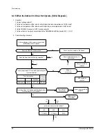
1. Check if the connector was normally assembled.
2. Put the set in operation and check the voltage of No. 3(+) and No. 2(-) of the main PCB CN91 while operating the
remote control. When the voltage descends below 3V, the assembly module PCB is normal and the main PCB is poor.
Then replace the main PCB.
3. Replace the assembly display PCB because the module PCB is poor if the voltage between No. 2~3 of CN91
maintains 5V after the remote control starts operation.
DB98_16999A(2)_1 04/3/12 10:27 AM Page 24
Summary of Contents for SC07AS2
Page 4: ...3 Samsung Electronics 1 2 Pressure Graph SC07AS2 SC07AS2A SC09AS2 SC12AS4...
Page 26: ...MEMO 25 Samsung Electronics...
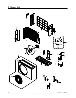
Page 31: ...Samsung Electronics 30 7 3 Ass y Control In Indoor Unit SC07AS2 SC07AS2A SC09AS2 DB93 02524B...
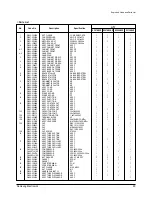
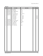
Page 33: ...Samsung Electronics 32 Exploded Views and Parts List SC12AS4 DB93 02539B...
Page 36: ...35 Samsung Electronics 9 PCB Diagram 9 1 ASS Y MAIN PCB 7K 9K 12K DB93 02447B TOP...
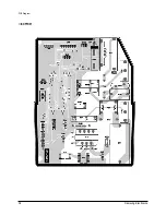
Page 37: ...Samsung Electronics 36 PCB Diagram BOTTOM...
Page 44: ...MEMO 43 Samsung Electronics...
Page 45: ...MEMO Samsung Electronics 44...

