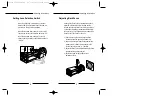
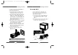
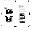
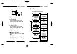
background image

Super WDR & Low Light
Digital Color Camera

SCC-833(P)
SCC-835(P)
SCC-803P/805P

Part  No.: AB68-00107A
Printed  in  Korea

Operating Instructions

00107A SCC-833P/855P - gb  11/22/00 3:36 PM  Page 44

Summary of Contents for SCC-803P

Page 1: ...Super WDR Low Light Digital Color Camera SCC 833 P SCC 835 P SCC 803P 805P Part No AB68 00107A Printed in Korea Operating Instructions 00107A SCC 833P 855P gb 11 22 00 3 36 PM Page 44 ...

Page 2: ...tion and Use 5 Connecting Auto Iris Lens Connector 6 Mounting lens 7 Setting Lens Selection Switch 8 Adjusting Back Focus 9 Connecting Cable 11 4 Name and Functions of Parts 14 Name and Functions of Camera Parts 14 Camera Setup 19 5 Product Specifications 39 00107A SCC 833P 855P gb 11 22 00 3 36 PM Page 1 ...

Page 3: ... to the ideal combination of the excellent performance of the high light compression Knee Compensation function and the BLC Back Light Compensation function 3 Operating Instructions 1 Overview Adopting the latest Super HAD CCD Charge Coupled Device the CCTV COLOR CAMERA SCC 833 P 835 P 803P 805P are monitoring camera which can provide the best monitoring function when connected to the CCTV system ...

Page 4: ...tandards Remote control using PC requires additional RS485 232C Interface Jig Operating Instructions 4 3 Installation Precautions in Installation and Use 1 Do not attempt to disassemble the camera yourself 2 Be cautious in handling the camera Avoid striking or shaking the camera Make sure to avoid damage on the camera caused by improper storage or operation 3 Do not expose the camera to rain or mo...

Page 5: ...rol Type 1 Damp Power 9V 2 Damp Not used 3 Drive Video signal 4 Drive GND Rib Pin1 Pin2 Pin3 Pin4 Mounting the Lens Loosen a screw fixing the Flange Back Adjustment Ring by turning it counterclockwise and turn the Adjustment Ring to the C direction counterclockwise until it stops Failure to do so may result in a damage caused by a bump of the lens against the image sensor part in the camera when m...

Page 6: ...the Back Focus of the camera has been adjusted in the factory before its shipment the focus may not be accurate for a certain type of lens In this case follow the procedures below to adjust the back focus First following is how to adjust the Back Focus of the Fixed Focus Lens 1 Lightly loosen up the screw fixing the Back Focus Adjustment Ring using a screwdriver 2 Image a vivid subject with check ...

Page 7: ...wo to three times to exactly coincide the zoom focus from TELE with that from WIDE 5 Fasten the screw fixing the Back Focus Adjustment Ring Note Turning the Back Focus Adjustment Ring to the C direction beyond the adjustable range makes a sound at the limit LENS DC VIDEO Connecting Cable After mounting the lens and setting the Lens Selection switch connect the prepared cable to each terminal of th...

Page 8: ...e power adapter using a screwdriver to the Power In Terminal of the camera as shown below Connect to the AC 24V or DC 12V power source without the distinction of the polarity LENS 110 220 DC VIDEO AC24V DC12V 4 Connect the power input cord to the AC 230V power source SCC 803P 805P LENS DC VIDEO 00107A SCC 833P 855P gb 11 22 00 3 36 PM Page 12 ...

Page 9: ...tly with a tissue for lens or a cotton cloth applied with ethanol Auto Iris Lens Connector Used for supplying power which is required to control the iris of the lens as well as control signal video signal or DC signal to the Auto Iris Control Lens Auto Iris Lens Control Cable Used for transmitting the control signals to the camera to control the iris of the lens Flange Back Adjustment Ring Used fo...

Page 10: ... video signal is output 3 Remote Input Terminal RS485 control This is a connection terminal used to adjust the camera in the factory and it can be controlled remotely using RS485 Half Duplex 4 Alarm Signal Output Alarm signal is generated when Motion Detection of camera occurs ALARM OUT GND PWR AC 220 240V REMOTE VIDEO OUT 4 2 1 6 5 3 ALARM OUT GND PWR REMOTE AC 24V DC 12V VIDEO OUT 6 2 1 4 5 3 1 ...

Page 11: ...ect it to AC 230V power cable SCC 833 P 835 P Connect it to AC 24V DC 12V power adapter 4 2 1 3 5 Camera Setup Setup menu is configured as follows S E T U P M E N U CAMERA ID OFF ON ON Write an ID Select the position SENSE UP OFF FIX X2 32 AUTO X2 32 ALC ELC ALC ELC ALC WDR OFF AUTO ON Adjust Level SHUTTER OFF 100K Adjust Iris BLC OFF ON ON AREA POSITION Adjust Position PRESET OFF ON MANU PRESET 3...

Page 12: ...ID SENSE UP ALC ELC BLC AGC WHITE BAL SYNC VIDEO CON MOTION DET EXIT Flickering Indicates that SUB MENU exists 1 Indication of the Main Menu Press the Setup Switch for about two to three seconds then the Setup Menu Main Menu will be shown as seen in the diagram below 2 Indication of the Sub Menu mark next to the item indicates that there is a sub menu under the main Move the cursor to the item wit...

Page 13: ... When all the characters you want are entered move the cursor to LOCATION and press the Setup Switch to have the menu that allows you to change the location of camera ID The location of the camera ID can be changed and fixed using the up down right left direction switch Press the Setup Switch for 2 to 3 seconds after the location is selected to return to the previous Sub Menu screen Place the sele...

Page 14: ... FIX X6 FIX X8 FIX X12 FIX X16 FIX X24 FIX X32 When ALC ELC MODE is set as ALC when WDR is AUTO OFF AUTO X2 AUTO X4 AUTO X6 AUTO X8 AUTO X12 AUTO X16 AUTO X24 AUTO X32 When the WDR on the ALC MENU is set ON Sense Up Function cannot be operated at the same time Data is not switched to FIX Only when WDR is set OFF it can be switched to FIX and in this case WDR on the ALC LENS MENU is indicated as an...

Page 15: ...0 10K 20K 30K 50K 100K PAL When OFF is set WDR function is not available and level is not indicated When ON is set level is indicated Move the cursor to the Level item and use the right left direction switch to adjust WDR level When WDR is ON Shutter is indicated as and its setting is not to be changed When Auto is set WDR function is automatically made on or off based on the counter light status ...

Page 16: ...te where IRIS DATA is set IRIS Setting Move the cursor to IRIS and adjust the relevant data using right left direction switch Iris value of the DC lens is determined by the selected data For Video lens the iris value is determined by the data value only when the BLC motion is set ON 2 Setting ELC Menu First select ELC on ALC ELC Menu and select the LEVEL Target level can be adjusted using the righ...

Page 17: ... DET EXIT When ATW selected Auto White Balance Control is on When AWC is selected White Balance Control memorized previously utilizing AWC is on When setting new AWC condition press the Setup Switch while AWC is selected Then AWC becomes flickering and White Balance Control is operated to memorize the data When the setting is completed the flickering stops While ATW always calls White Balance AWC ...

Page 18: ...ion switch If the camera is set to INT Internal Sync mode when monitoring in the Auto Switching mode with more than one camera connected to a sequential switcher etc the jump of the screen will occur each time of screen switching To switch the screen gently without a jump set the camera to L L and adjust the Vertical Sync Phase However L L function can be used only when using AC power This setting...

Page 19: ...ultiple number of cameras is used Address to control each camera should be set using RS485 communications Adjusting H DTL refer to the diagram on page 36 Move the cursor to H DTL horizontal edge adjustment and change the value using the right left direction switch The value can become or starting from 0 using the right left direction switch Adjusting V DTL refer to the diagram on page 36 Move the ...

Page 20: ...MOTION is detected ALARM OUT terminal becomes Gnd and the ALARM is lifted automatically about 30 seconds later GND OPEN VIDEO CONTROL 0 POSI OFF OFF RS485 ADDR H DTL V DTL POSI NEGA H REV V REV RET The setting of the MOTION DET MENU is as follows Move the MOTION DETECT range selection cursor to AREA SET and press the Setup Switch to see the MOTION AREA Select the AREA location using the right left...

Page 21: ...light compensation location setting possible ELC Electronic Iris function Operating Instructions 38 Setting the LEVEL Move the cursor to LEVEL and choose MOTION DETECTION LEVEL within the selected range using the right left selection switch 10 EXIT MODE Move the cursor to EXIT and select QUIT SAVE PRESET using the right left direction switch Set QUIT and press the Setup Switch to return to the ori...

Page 22: ...imes Sense Up Up to 32 times OFF FIX X2 FIX X32 AUTO X2 AUTO X32 BLC Back light compensation location setting possible ELC Electronic Iris function Operating Instructions 40 Item Details Shutter Setting OFF 1 100K seconds 16 steps Motion Det Motion detection Alarm Out ID Setting Up to 12 characters location setting Color Temperature ATW AWC MANUAL MODE Setting 3200 K 5600 K R B Gain adjustment Sig...

Page 23: ...0 C Temperature Operating Environment 90 Humidity Size 65 W 52 H 133 L mm BNC included Weight 833P 835P 450g 803P 805P 550g Altitude 3 000M or less RS 485 Remote Control This is RS 485 Protocol about keys of SCC 833 Target Address is able to change in sub menu of VIDEO CONTROL SCC 833 Default value of target address is 0 The below value is hexadecimal Port Setting Baud Rate 38400 bps Data Bits 8 b...

Page 24: ...Super WDR Low Light Digital Color Camera SCC 833 P SCC 835 P SCC 803P 805P Part No AB68 00107A Printed in Korea Operating Instructions 00107A SCC 833P 855P gb 11 22 00 3 36 PM Page 44 ...

Reviews: