background image

Setup

24_ Setup


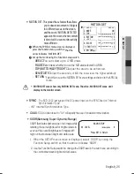
CAm TITle :


If you enter a title, the title will appear on the monitor.


  1 

If the SPECIAL menu scr


CAMERA TITLE SETUP

A B C D E F G H I J K L M
  N O P Q R S T U V W X Y Z
  a b c d e f g h i j k l m
  n o p q r s t u v w x y z


 ← →

  C L R   P O S   E N D

_ _ _ _ _ _ _ _ _ _ _ _ _ _ _

een is displayed, use the Function Setup switch so 

that the

    arrow indicates ‘CAM TITLE’. 


  3 

Press the Function Setup switch.

Set it to ‘ON’ by using the Function 

Setup  

   switch.


Use the Function Setup switch to move to a 

0 1 2 3 4 5 6 7 8 9

/

- .

PRIVACY AREA SETUP


 1.AREA 


AREA1

   2.MODE 


OFF

   3.MASK COLOR  

GREEN


 4.SEL POS 


LEFT


 5.POS 


*

IIIIIIIIIIIIIIIIIIIIIIIIII


42


 6.RETURN


pRIVACy 

: Mask an area you want to hide on the screen.

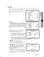
  When the SPECIAL menu screen is displ-

ayed, press the Function Setup switch so

 that the arrow indicates ‘PRIVACY’.

2  


-

AREA : You can select up to 8 PRIVACY areas.

Set up the mode using the Function Setup

 switch.


-

MODE : Determines whether to use the ar


-


-

SEL POS/POS : Adjust the size and position of the selected area.


-

RETURN : Select this to save the PRIV


 WHITE and GRAY.

MASK COLOR : Determine area color. You can select GREEN, RED, BLUE, BLACK,

ACY menu settings and return to the SPECIAL

 menu.

ea 

selected.


  When the CAM TITLE menu is ‘OFF’, no title will be displayed on the monitor screen even 

if you enter one.

  Only English is available in this mode.

  If you move the cursor to CLR and press the Function Setup switch, all the letters are 

deleted. To edit a letter, change the cursor to the bottom left arrow and press the 

Function Setup switch. Move the cursor over the letter to be edited, move the cursor to 

the letter to be inserted and then press the Function Setup switch.


desired letter and select the letter by pressing

 the switch. Repeat this to enter multiple letters.

 You can enter up to 15 letters. Move the 

cursor to   for entering a space, then press

 the Function 

 Enter a title, move the cursor to ’POS’ and press

 the Function Setup switch. The entered title appears

 on the screen. Select the position to display the title

 on the screen by using the Function Setup switch

 and press. When the position is determined, select

return to the SPECIAL menu.

 ’END’ and  press the Function Setup switch to 

Setup switch, the cursor will skip

 to the next.

 FRONT DOOR

Summary of Contents for SCD-2022

Page 1: ...High Resolution Dome Camera User Manual SCD 2022 ...

Page 2: ...contents in this document but no formal guarantee shall be provided Use of this document and the subsequent results shall be entirely on the user s own responsibility Samsung Techwin reserves the right to change the contents of this document without prior notice Warranty If the product does not operate properly in normal conditions please let us know Samsung Techwin will resolve the problem for fr...

Page 3: ...firm the camera model and correct input power voltage To help you understand this manual thoroughly we ll introduce our model description POWER SOURCE SCD 2022N SCD 2022P DC12V SCD 2022 SERIES PAL MODEL SCD 2022P NTSC MODEL SCD 2022N ...

Page 4: ...zard do not expose this appliance to rain or moisture To prevent injury this apparatus must be securely attached to the floor wall in accordance with the installation instructions WARNING Be sure to use only the standard adapter that is specified in the specification sheet Using any other adapter could cause fire electrical shock or damage to the product Incorrectly connecting the power supply or ...

Page 5: ... Do not drop objects on the product or apply strong shock to it Keep away from a location subject to excessive vibrationor magnetic interference Do not install in a location subject to high temperature over 55 C low temperature below 10 C or high humidity Doing so may cause fire or electric shock If you want to relocate the already installed product be sure to turn off the power and then move or r...

Page 6: ... accessories or literature indicates that the product and its electronic accessories e g charger headset USB cable should not be disposed of with other household waste at the end of their working life To prevent possible harm to the environment or human health from uncontrolled waste disposal please separate these items from other types of waste and recycle them responsibly to promote the sustaina...

Page 7: ...the obsolete outlet Protect the power cord from being walked on or pinched particularly at plugs convenience receptacles and the point where they exit from the apparatus Only use attachments accessories specified by the manufacturer Use only with cart stand tripod bracket or table specified by the manufacturer or sold with the apparatus Unplug this apparatus when a card is used Use caution when mo...

Page 8: ... Menu Configration Menu Setup TROUBLESHOOTING 27 Troubleshooting SPECIFICATIONS Specifications 7 18 18 18 Contents 8_ Contents 2 28 28 Dimension 30 12 Installation 15 16 Using coaxial communications Connecting to Power Adjust the panning and tilting rotating while watching the monitor 2 CONNECTION 15 15 Connecting to Monitor ...

Page 9: ...tically defog correct image of the bad weather such as fog rain mist fumes etc to make it clear For images with high contrast between bright and dark areas from difficult lighting conditions such as backlighting this camera selectively illuminates darker areas while retaining thesame light level for brighter areas to even out the overall brightness are provided Communication Coaxial communication ...

Page 10: ...Introduction WHAT S INCLUDED Check if the following items are included in the product package 10_ Introduction SCD 2022 Tapping Screw 3EA SCD 2022 Quick Manual HighResolutionDomeCamera Quick Manual ...

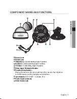
Page 11: ...ve the cursor to four directions to confirm status or after changing a selected item 8 Dome Cover Shield Case Rotate Base Control rotating angle of camera Pan Base Control panning angle of camera 5 Tilt Base Control tilting angle of camera 6 Video Output Terminal to Monitor Video Output Jack 9 Power Input Connector Lens Module SCD 2022P f 3 8mm F2 0 ...

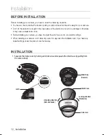
Page 12: ... cause a breakdown or fire Before installing your camera you have to adjust the lens focus zoom and switch settings When installing your camera don t allow any person to approach the installation site If you have any valuable things under the place move them away INSTALLATION 12_ Installation 1 Separate the dome cover by turning anti clockwiseandseparate the shield case by pulling from the camera ...

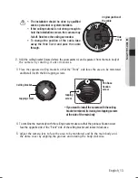
Page 13: ...ate it from the main body of Place the separated ceiling bracket so that the Front side faces the area to be monitored and install it with the M4 tapping screws To combine the main body with the ceiling bracket make sure that the pan base fixation screw face the opposite side of the Front side of the ceilingbracket and rotate it clockwise Adjust the camera lens to face the area to be monitored and...

Page 14: ...mounting the camera on a wall adjusting the panning angle so that the camera can face the direction to monitor when tilted 2 Adjust the tilting angle by rotating the tilt base 3 Loosen the rotate base hold screw and adjust rotate base for the best view 4 Tighten the rotate base hold screw The case of ceiling installation 1 After mounting the camera on a ceiling adjusting the panning angle to the c...

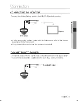
Page 15: ...le when the power is turned off As the connecting method varies with the instruments refer to the manual supplied with the instrument CCTV Camera Monitor Connect the adaptor to the power input connector as shown in the figure below The recommended adaptor specification for SCD 2022 is DC12V 500mA CONNeCTING TO pOWeR Power Input Terminal ...

Page 16: ...erformance of the camera Standard voltage for camera operation There may be some deviation in voltage drop depending on the type of wire and the manufacturer Be sure to connect power only after all the installation is complete Note that DC adaptor is not supplied with camera UsING COAxIAl COmmUNICATIONs Coaxial Communications System OSD Control method CAMERA SET UP DOWN LEFT RIGHT DVR CONTROLLER M...

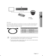
Page 17: ...s video output port is connected to the monitor with a BNC coaxial cable shown below If the distance between the camera and the monitor exceeds the recommended maximum please use an auxiliary video amp Distance Recommended Cable Specification 300m 3C2V RG 59 U 450m 5C2V RG 6 U 600m 7C2V RG 11 U It is recommended that pure copper coax cable is used and not copper coated steel as this will cause iss...

Page 18: ...GHTNESS AGC SENS UP RETURN OFF AUTO MANUAL ATW OUTDOOR INDOOR MANUAL AWC SET OFF ON OFF AUTO COLOR B W CAM TITLE PRIVACY SYNC RETURN IMAGE ADJ MOTION DET SAVE NOT SAVE RESET Use the Function Setup switch within the camera Function Setup switch meNU seTUp 1 Press the Function Setup switch Main setup menu is displayed on the monitor screen ...

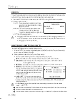
Page 19: ...ect a sub menu select an item with the icon and press the Function Setup switch expOsURe 1 When the SETUP menu screen is displayed select EXPOSURE by using the Function Setup switchso that the arrow indicates EXPOSURE 2 Select a desired mode using the Function Setup switch BRIGHTNESS Adjuststhevideobrightness AGC AUTOGAINCONTROL butthehigherthenoise OFF LOW MID HIGH Thehigherthegainlevel thebright...

Page 20: ...etween1 700 Kand11 000 K WhentheSETUPmenuscreenisdisplayed select WhiteBal byusingtheFunctionSetupswitch sothat thearrowindicates WhiteBal OUTdOOR INdOOR Select this when the color temperature is between 4 500 K and 8 500 K Selectthiswhenthecolortemperatureisbetween1 700 Kand11 000 K sodiumlightinclusion MaNUal Selectthistofine tuneWhiteBalance manually SetWhiteBalancefirstbyusingtheATW orAWCmode ...

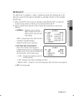
Page 21: ...rly LEVEL Adjust level of the BLC function TOP BOTTOM LEFT RIGHT Adjust the area to be enhanced BLC SETUP 1 LEVEL MIDDLE 2 TOP IIIII IIIIIIIIIIIIIIII 81 3 BOTTOM IIIIIIIIIIIIIIIIII III 181 IIIIII IIIIIIIIIIIIIII 211 5 RIGHT IIIII 461 6 RETURN IIIIIIIIIIII IIII HlC High light Compensation This function masks the strong light to minimize white out due to over exposure and preserve much of the on scr...

Page 22: ...isplay pictures in color or black and white 1 When the SETUP menu screen is displayed select DAY NIGHT by using the Up and Down buttons so that the arrow indicates DAY NIGHT 2 Select a desired mode using the Left and Right buttons according to the picture display you want AUTO SETUP DWELL TIME 5 SEC BURST MODE ON Press SET to Return AUTO BURST MODE You can turn on or off the burst mode on B W mode...

Page 23: ...IIIIIIIIIII 15 COLOR GAIN IIIIIIIII IIIIIIIIIIII 5 RESET Press SET to Return monitor Please change the settings value of video appropriate to your monitor LCD Pleaseselectthismenuitemwhenusing anLCD monitor Youcanchangethegamma PEDlevelandcolor gaininthesubmenus USER Pleaseusethismenuitemwhenusing a monitorother than standard ones You can change the gamma PED level and color gain in the sub menus ...

Page 24: ...RETURN Select this to save the PRIV WHITE and GRAY MASK COLOR Determine area color You can select GREEN RED BLUE BLACK ACY menu settings and return to the SPECIAL menu ea selected When the CAM TITLE menu is OFF no title will be displayed on the monitor screen even if you enter one Only English is available in this mode If you move the cursor to CLR and press the Function Setup switch all the lette...

Page 25: ...ITY Adjust the sensitivity of MD the lower level the higher sensitivity SelectthistosavetheMOTIONDETmenusettingsandreturntotheSPECIAL menu MOTION DET areas show only MOTION DETmenu Therefore MOTION DET areas don t display on the monitor screen syNC The SCD 2022 just support the DC power input so the SYNC fixed on Internal Synchronization Type INT Internal Synchronization Type COaX COAX option is s...

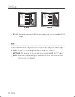
Page 26: ... Select a desired EXIT mode using the Function Setup switch depending on the camera purpose sAVe Save the current settings and exit the MAIN SETUP menu NOT sAVe Do not save the current settings and exit the MAIN SETUP menu ReseT Resets the camera settings to the factory defaults Monitor and COAX settings are not initialized ...

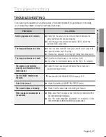
Page 27: ...ong light change the camera position The image on the screen is dark Adjust the contrast feature of the monitor or DVR If you have an intermediate device set the 75Ω Hi z properly The camera is not working properly and the surface of the camera is hot Check that you have properly connected the camera to an appropriate power source The DAY NIGHT function does not work Check thatAGC of EXPOSURE SETU...

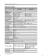
Page 28: ...e Imaging Device Total Pixels Effective Pixels Scanning System Synchronization Frequency Horizontal Resolution Min Illumination Video Output s N Ratio Lens Type Focal Length Max Aperture Ratio Angular Field of View Min Object Distance Lens Type Mount Type PAN TILT ROTATE Pan Tilt Rotate Range Operational English Japanese Spanish French Portuguese Korean English French German Spanish Italian Chines...

Page 29: ...ntrol SPC 300 Compatible Coax Pelco C Coaxitron OFF H REV 10 C 55 C 14 F 131 F Less than 90 RH 23 3 g Backlight Compensation SSDR SSNR3 Defog Privacy Masking Motion Detection Gain Control Electronic Shutter Speed White Balance Reverse Communication Protocol Environmental Operating Temperature Humidity Electrical Input Voltage Current Mechanical Dimension Weight ATW Outdoor Indoor Manual AWC SET 1 ...

Page 30: ...Specifications DIMENSION Unit mm Ø107 6 R45 83 7 81 6 30_ Specifications ...

Page 31: ...MEMO ...

Page 32: ... FAX 82 31 8018 3745 SAMSUNG TECHWIN EUROPE LTD Samsung House 1000 Hillswood Drive Hillswood Business Park Chertsey Surrey UNITED KINGDOM KT16 OPS TEL 44 1932 45 5300 FAX 44 1932 45 5325 SAMSUNG TECHWIN AMERICA Inc 100 Challenger Rd Suite 700 Ridgefield Park NJ 07660 Toll Free 1 877 213 1222 Direct 1 201 325 6920 Fax 1 201 373 0124 www samsungcctvusa com SALES NETWORK PT01 001709A P NO ...

Reviews: