Samsung SCD-5083, User Manual
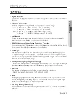
The Samsung SCD-5083 is a high-performance surveillance camera packed with advanced features. Capture crisp and detailed images with its 1000TVL resolution and benefit from enhanced low-light performance. Easily set up and optimize your camera's settings by accessing the free user manual available for download at 88.208.23.73:8080.
Share
Download


Reviews:
No comments
Related manuals for SCD-5083

PC88WR
Brand: Super Circuits Pages: 2

DCS-5010L
Brand: D-Link Pages: 2

DCS-936L
Brand: D-Link Pages: 8

2
Brand: OCO Pages: 11

A1
Brand: Ultrative Pages: 9

5
Brand: FED Pages: 5

EXPCMR-ALG-OZ-IC-1080PLE1-1227-250C-QD-15C-12.4
Brand: LARSON Pages: 4

VB-C300
Brand: Canon Pages: 54

VB-C300
Brand: Canon Pages: 54

Vb-C60 - Ptz Network Camera
Brand: Canon Pages: 76

DCS-820L
Brand: D-Link Pages: 16

DCS-2530L
Brand: D-Link Pages: 6

DCS-2136L
Brand: D-Link Pages: 8

DSH-C310
Brand: D-Link Pages: 2

DCS-820L
Brand: D-Link Pages: 4

DCS-8330LH
Brand: D-Link Pages: 41

DCS-932L
Brand: D-Link Pages: 40

DCS-930L
Brand: D-Link Pages: 2


