background image

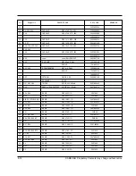
8-22

SAMSUNG Proprietary-Contents may change without notice

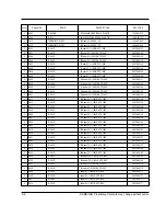
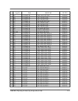
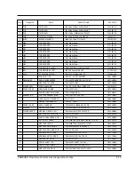
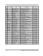
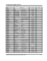
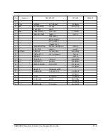
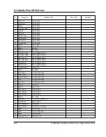
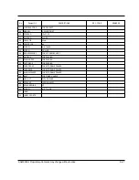
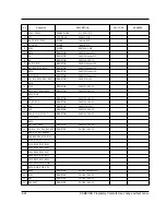
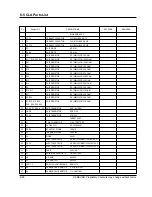
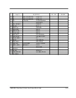
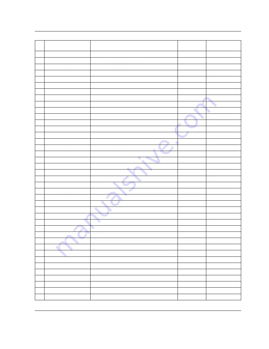
No

Design LOC

DESCRIPTION

REMARKS

SEC. CODE

1

2

3

4

5

6

7

8

9

10

11

12

13

14

15

16

17

18

19

20

21

22

23

24

25

26

ZENER DIODE

TVS DIODE

DIODE

DIODE

DIODE

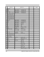
RESISTOR

RESISTOR

RESISTOR

RESISTOR

RESISTOR

RESISTOR

RESISTOR

RESISTOR

RESISTOR

RESISTOR

RESISTOR

RESISTOR

RESISTOR

RESISTOR

RESISTOR

RESISTER

RESISTER

RESISTER

RESISTER

RESISTER

RESISTER

5.1V 0.5W - DIP

P6KE33 - DIP

1N4148 - DIP

1N5818 - DIP

SDS7000 - CHIP

CH2012 1ohm-J 5%

CH2012 91oohm-F 1%

CH2012 8.2K-F 1%

CH2012 100ohm-J 5%

CH2012 220ohm-J 5%

CH2012 270ohm-J 5%

CH2012 330ohm-J 5%

CH2012 1K-J 5%

CH2012 1.8K-J 5%

CH2012 2.2K-J 5%

CH2012 2.4K-J 5%

CH2012 2.7K-J 5%

CH2012 3K-J 5%

CH2012 3.9K-J 5%

CH2012 4.7K-J 5%

CH2012 5.1K-J 5%

CH 2012 10K-J 5%

CH 2012 560 ohm-J 5%

CH 3216 10K-J 5%

CH 3216 12K-J 5%

CH 3216 10K-J 5%

ZD201, ZD202

ZD1

D5, D7, D101, D102

D1, D2, D3

D100

R278

R9

R8

R3, R13, R131

R51, R52, R139, R272

R279

R137, R138

R31, R32, R225, R251, R257,

R270

R132

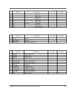
R213, R217, R228, R229,

R230,  R231

R271

R1, R7, R112

R18

R12

R38, R110,  R113, R117,

R119, R268

R275

R57, R233, R248

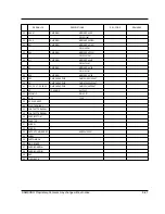
R5, R10,  R17, R20,  R23,R27

R30,  R33, R41, R44 R45,

R46, R55, R56, R100. R104,

R108, R109, R111,  R115,

R116, R120,  R122, R123,

R124, R135, R201, R202,

R203, R204, R205, R207,

R208, R210,  R211, R212,

R215, R252, R253, R254,

R255, R258, R260,  R266,

R270,  R274, R276, R114

R269

R102

R43

R54, R267

Summary of Contents for SCH-811

Page 1: ...MSUNG PROPRIETARY CONTENTS MAY CHANGE WITHOUT NOTICE CONTENTS 1 General Introduction 2 Specification 3 Installation 4 NAM Programming 5 Product Support Tools 6 Troubleshooting 7 Exploded view and its Part List 8 Electrical Parts List 9 PCB diagrams 10 Block circuit diagrams ...

Page 2: ...Samsung Electronics Co Ltd GH68 00398A 1999 3 REV 1 0 ELECTRONICS ...

Page 3: ...logies are combined into this phone to reduce the call drop while usage CDMA digital cellular network consists of MSO Mobile Switching Office BSC Base Station Controller BTS Base Station Transmission System and MS Mobile Station MS meets the specifications of the below E IS 95A Mobile Station Base Station Compatibility Standard for Dual Mode Wideband Spread Spectrum Cellular System E IS 96A Speech...

Page 4: ... 60ûC 4ûF 140ûF Operating Temperature 30ûC 60ûC 4ûF 140ûF Operating Voltage HHP 3 6V DC 10 Hands free 13 7V DC 10 Size and Weight 88 0 x 56 5 x 26 7 27 6 31 3 mm including slim battery 117 3 g including standard battery 145 2 g including extended battery 160 5 g Operating Time Digital Mode Standby Time up to 36 hours with slim battery up to 65 hours with standard battery up to 100 hours with exten...

Page 5: ...dBm Tx Frequency Deviation 300Hz or less Occupied Band Width 1 32MHz Tx Conducted Spurious Emission 900KHz 42dBc 30KHz below 1 98MHz 54dBc 30KHz below Minimum Tx Power Control below 50dBm 25dBm 57 0dBm 38 5dBm Open Loop Power Control 65dBm 17 5dBm 1 5dBm 104dBm 18 0dBm 30 0dBm Standby Output Power below 61dBm Test1 24dB or less Test2 0mS 2 5mS Colsed Loop Tx Power Control Range Test3 24dB or more ...

Page 6: ...0KHz f0 45KHz For modulation by voice and SAT f0 45KHz For modulation by WBD without SAT and ST with SAT f0 45KHz f0 60KHz f0 60KHz f0 90KHz f0 90KHz 2f0 Harmonic and conducted Spurious Emissions 0 6W 2 4dB within 3dB of specification output in 2mS below 60dBm in 2mS 2 1 3mS 13 5mS Input level for producing a nominal 2 9KHz peak freqency deviation of transmitted carrier 6dB OCT within 0 3 3KHz 12K...

Page 7: ... Band Conducted Spurious Emission Transmit Band Receive Band Other Band Radiated Spurious Emission Frequency Range 25 70 MHz 70 130MHz 130 174 MHz 174 260 MHz 260 470 MHz 470 1GHz 6dB OCT within 0 3 3KHz 1 2 within 3mS within 13 5mS output level to a 1000Hz tone from a carrier within 2 9KHz peak frequency deviation 12dB SINAD 116dBm avove 65dB above 60dB above 60dB below 60dBm below 80dBm below 47...

Page 8: ... Handset Status 0 Acquisition 1 Synchronization 2 Paging Idle 3 Traffic Initialization 4 Traffic Mode 5 Exit 4 T xx Tx adjust Value ranges from 63 63dB 5 Dxxx sector power in dBm 6 xx Ec Io 7 Pxxx PN offset 8 CHxxxx channel number 9 TEx Tx vocoder rate 8 is full rate 1 is 1 8th rate E EVRC V 13k or 8k 10 REx Rx vocoder rate 8 is full rate 1 is 1 8th rate 11 xx Walsh code used in traffic channel 1 ...

Page 9: ... 5 FM Debug Display Information menu 8 1 SIDxxxxx FM Home System ID 2 PWRx Power Level 0 7 3 SATx Supervisory Audio Tone code 0 3 4 x Using Frequency Band A Band or B Band 5 RSSIxxx RSSI value 6 CHxxx Using Channel 1 4 5 2 SIDxxxxx PWRx RSSIxxx CHxxxx SATx x 3 6 ...

Page 10: ...ge contacts pointing downward 2 Slide the battery pack upwards until it clicks firmly into position The phone is now ready to be turned on 3 To remove the battery pack release it by pressing the button on the rear of the phone 4 Slide the battery pack downward about 1cm 1 2inch and lift it away from the phone 3 1 SAMSUNG Proprietary Contents may change without notice Press this button to release t...

Page 11: ... the battery insert the phone with the battery pack attached into the front slot of the charger The lamp marked PHONE on the front panel of the charger lights up red Figure 3 1 Charging the Phone and Battery SPECIFICATIONS USING ÒDTC 81Ó Product Charging time hours Stand by time hours Talking time min Front Rear Digital Digital Slim Battery Pack Li ion 550mAh 2 2 36 75 Standard Battery Pack Li ion...

Page 12: ...ll by using the screws 4 Place the cradle onto the remaining half of the clamshell and assemble them by using the screws 5 Reassemble the two halves of the clamshell together Adjust the mounting angle and tighten the two slotted screws Figure 3 2 Cradle Installation 3 3 2 Hands Free Box 1 Drill holes in a proper location for the hands free box attach the mounting bracket by using the screws See th...

Page 13: ...h away from the driver Choose the location where is least susceptible to interference caused by external noise sources ie adjacent windows radio speakers etc Normal place is the sun visor 2 Once the microphone has been correctly positioned connect the microphone wire to the MIC jack on the hands free box Figure 3 3 Hands Free Box 1 Installation MOUNTING BRACKET ...

Page 14: ...itched side of the ignition switch and then connect the white to the stereo mute wire from your vehicle stereo 4 Connect the other end of the power cable to the PWR jack of the hands free box Notes It is recommended to connect the power cable directly to the battery to avoid power noise Make sure the connection in the vehicle between the battery terminal and vehicle chassis is made correctly Make ...

Page 15: ...f the phone is displayed E9031F77 CAI version Volumet Common Air Interface version is displayed 3 VOC13K 8K SO_VOICE_08K Volume Vocoder Rate SCM Volume Station Class Mark displays the power class 01101010 transmission slotted class dual mode Lock Code Lock code current ststus is displayed 0000 4 digit code to change enter new code OK store it Slot Mode Slot mode ÔYesÕ indicates the slot mode Yes F...

Page 16: ...Phone Õ 1 Phone 2 FM 3 CDMA FM HOME SID System ID for home current ststus is displayed 4369 ID number to change enter new one OK store it FM 1st Chn Current 1st paging channel 333 Channel number to change enter new one OK store it FM Acq SID1 Acquisition system ID 1 current status is displayed 4 ID number to change enter new one OK store it FM Acq SID2 Acquisition system ID2 current status is disp...

Page 17: ...r new one OK store it IMSI_MNC IMSI Mobile Network Code current code is displayed 00 number to change enter new one OK store it CDMA pref Preferred system selection current system is displayed A only F or E changes the system OK store it CDMA ACCOLC CDMA Access Overload Class current status is displayed 0 class number to change enter new one OK store it Pchn Sys A Preferred channel currently used ...

Page 18: ...or E changes the system OK store it CDMA fNID CDMA foreign NID current status is displayed Yes F or E changes the system OK store it SID 1 first SID written in the list current status is displayed 2222 number to change enter new one OK store it NID 1 first NID written in the list current status is displayed 1 number to change enter new one OK store it SID 2 2nd SID written in the list current stat...

Page 19: ...2 Setting Up NAM1Õ LCD Display Key in Function SID 4 4th SID written in the list current status is displayed 2222 number to change enter new one OK store it NID 4 4th NID written in the list current status is displayed 15 number to change enter new one OK store it Setup NAM1 LCD returns to the NAM1 setup mode 1 Phone 2 FM 3 CDMA ...

Page 20: ... PST Software with appropriate cable DM Cable for SAMSUNG CDMA phone 3 Serial Port 16550 Serial Interface Card 4 POWER SUPPLY 3 8V OR BATTERY INSTALLATION Software 1 Insert the PST floppy disk into drive A 2 Create an appropriate directory on the C drive for PST software Execute Setup exe file The installation program creates folder and task bar on the windows95 98 start bar SAMSUNG CDMA Phone The...

Page 21: ...enÓ icon to select the name of a file whose extension is ÒmmcÓ The values will be read from the named file and will initialize the parameter values seen on the Service programming screen Read Data from Phone Click Read from the Phone icon to upload the current programmable parameters of the phone The values are read from the phone so the phone must have the power ON and be properly connected to th...

Page 22: ...Ó feature it is recommended that you do a ÒRead Data from PhoneÓ first and then make the changes so that nothing gets inadvertently overwritten NOTE DO NOT TOUCH THE PHONE WHILE WRITING IS IN PROGRESS Software Download and Upgrade Screen To begin a software upgrade or download perform the following steps 1 From the main menu screen choose DOWNLOAD MODE Click open icon to choose a BIN file of the n...

Page 23: ...RF Interface Pack AssÕy 1 Power Cable Black Red 2 9 pin RS232 data Cable CAUTION Because there is the loss 0 33V at FM Max Power of the test jig and Data cable youÕd better input 3 93V to the DC Power Supply to use 3 6V Battery normal voltage at Cellular phone Items needed to purchase from SAMSUNG Spectrum Analyzer HP8924C RF In RF In Out Audio Out Audio In Directional Coupler Test Jig To A Out To...

Page 24: ... IN RIGHT AUDIONOFF DC POWER INPUT PORT CHANGE VOLTAGE LEVEL BY MODEL 3 8VDC RED BLACK GND D89 CONNECTOR CONNECT TO IBM PC SERIAL PORT BJ11 CONNECTOR CONNECT TO HP SERIAL PORT NOT USED CONNECT TO AUDIO IN PORT OF TEST EQUIPMENT USE BNC CABLE CONNECT TO AUDIO OUT PORT OF TEST EQUIPMENT USE BNC CABLE DB25 CONNECTOR CPMMECT TO DB25 CONNECTOR OF TEST CABLE UP AUTO POWER ON DOWN NOT USE AUTO TO A OUT T...

Page 25: ...CABLE 6 Dsub 25PIN CONNECTOR DATA Dsub 25 PIN CONNECTOR PIN DESCRIPTION TEST CABLE 1 BACK SIDE DATA DESCRIPTION Dsub CONN DATA DESCRIPTION Dsub CONN PIN NO PIN NO V_F 12 21 DP_RX_DATA 8 DGND 2 4 6 13 19 HP_PWR 9 BATT 15 16 22 RI 10 C_F 3 20 CD 11 TX_AUDIO 5 RTS 14 DP_TX_DATA 7 CTS 17 RX_AUDIO 1 DTR 18 15 17 19 21 23 25 14 16 18 20 22 24 2 4 6 8 10 1 3 5 7 9 11 13 12 ...

Page 26: ...yÓ or ÒAnalog onlyÓ mode in NAM1 EST MODE Refer to 4 NAM Programming Channel Selection and Tx Power Output Level Control 1 Digital Mode CDMA A Enter to Test Mode 7 5 9 8 1 3 5 8 0 B Ò0 1Ó Suspend C Ò0 9 0 3 6 3 Ó Set to Ô0363Õ channel D Ò0 7Ó Carrier On E Ò3 4Ó Spread spectrum to 1 23MHz band width F Ò7 1 2 7 5 Ó Output RF power level setting Ò275Ó means AGC level and AGC level range is from 0 to ...

Page 27: ...t audio signal 15 89 1 0 T_VOC_ESEC_I Echo canceller ON OFF 16 8F 0 0 T_ST_ON_I Transmit a continuous Signaling Tone ST 17 90 0 0 T_ST_OFF_I Stop transmit a continuous Signaling Tone 19 93 0 0 T_INDEX_DECR_I Index dn Key 20 9E 3 0 T_LNA_GAIN_WR_I Write LNA gain 22 91 96 96 T_SNDNAM_I1 Display and send NAM information 23 95 3 4 T_SNDVERSION_I1 Display and return s w version 24 9F 7 8 T_SNDESN_I1 Di...

Page 28: ... path on 58 BD 0 0 T_MIC_OFF_I Mic path off 59 BE 0 0 T_ALLPATH_I Set Rx Path TX Path Unmute to Earpiece 60 BF 3 0 T_FM_TX_GAIN_I2 3 FM Tx Audio Gain Control 61 C0 3 0 T_FM_RX_GAIN_I2 3 FM Rx Audio Gain Control 62 C1 3 0 T_DTMF_VOL_TX_I2 3 FM Tx DTMF Gain control 63 C2 3 0 T_TX_LIMITER_I2 3 FM Tx Limiter Gain Control 64 C3 3 0 T_FM_SAT_LEVEL_I2 3 FM Tx SAT level Control 65 C4 3 0 T_FM_FREQ_SGAIN_I...

Page 29: ...ay 94 F4 4 0 T_HW_CHANFLAT_T H W Channel Flatness 95 F5 4 0 T_SW_CHANFLAT_T S W Channel Flatness 96 F6 3 0 T_CH_FLATNESS_I Set 22dBm Channel Deviation 10 POINT 97 F7 3 0 T_FM_TX_PWR_I Set FM PWR LEVEL 2 7 1 The AB Input Argument Byte Number values of these commands are used only in the manual test In automatic test mode the AB is regarded as 0 2 You can assign the value for these commands If the A...

Page 30: ... Check the signal from the battery terminal to U 105 pin 1 Check U105 and its neighboring circuits Check U106 and its neighboring circuits Check U107 and its neighboring circuits Press End button U105 pin 1 VBAT U106 pin 1 input 3 7V U106 pin 5 output 3 7V U107 pin 5 output 3 7V END Yes Yes Yes Yes No No No No ...

Page 31: ...f required Check U109 MSM and its neighboring circuits Check H level input from J104 pin 17 to U401 pin 79 replace if required Check Q125 and its neighboring circuit Replace if required Check the LCD pins and its neighboring circuit Replace if required TCXO CLK signal output from U401 pin 29 RAM CS signal output from U109 pin 44 CHIPX8 CLK signal output from U401 pin 52 Alert LED ON Normal initial...

Page 32: ...n the phone H level output from U101 L7 to J105 pin 19 H level input to U139 pin 4 5 Normal U139 operation Normal EL EL ON Check EL Replace if required Check U139 L201 Q139 and its neighboring circuits Replace if required Check FPC Replace if required Check U101 L7 Replace if required Yes No Yes No Yes No Yes No ...

Page 33: ...out notice 6 4 6 1 4 Abnormal Key Data input Check initial status Scanning signals output from U101 C5 B4 D5 A5 C6 A5 D6 Check U101 Check U101 A2 A3 C4 B5 E5 Check J103 Normal key data input Replace the key pad assembly END Yes Yes Yes Yes No No ...

Page 34: ...om U102 pin 14 15 16 Waveform output from U102 pin 2 3 Waveform applied to SPK normal key tone Check SPK Replace if required Check U102 R250 and C108 FPC Replace if required Check U102 pin 2 3 and its neighboring circuits Replace if required Check U102 pin 14 15 16 Replace if required END Yes Yes Yes Yes No No No No ...

Page 35: ... CLK waveform output from U102 pin 17 CLK waveform applied to Buzz Is the buzzer connection correct Connect the buzzer correctly Check Q120 Q121 R128 Replace if required Check U102 pin 17 and its neighboring circuits Replace if required Check U101 N7 P7 Replace if required Check the buzzer and replace if required Yes Yes Yes Yes No No No No ...

Page 36: ...OK Check 1st local mixer power OK Check PLL U306 VCO output Check IF filter in output OK Check IF filter soldering Check AGC amp in output OK Check 2nd local AGC control voltage OK Check PLL BBA 80 RF Rx FM OK Check Duplexer LNA power Yes Yes Yes Yes Yes Yes BBA INPUT 54dBm Gain 45dB Loss 5dB Gain FM 8dB Gain 17dB Gain 16dB VCO_OUTPUT 10dBm 969 96MHz local 4 0dBm 170 76MHz Yes Yes No No No No No N...

Page 37: ...ry Contents may change without notice 6 8 6 2 2 CDMA Mode Start CDMA mode Normal CDMA SVC ROAM Setup CDMA call OK Setup CDMA call OK Check Transmitter Check CDMA RX path Measure CDMA FER Normal CDMA RF Yes Yes No No No ...

Page 38: ... Tx Check Tx PLL Check Tx Power level Check U403 Out level Check U404 RF Out level Check U407 Pout level Check U403 Tx IF level Check U403 Local Input level Yes No No O K O K O K CDMA 20dBm SPAN 5MHz Tx VCO 260 76MHz IF 130 38MHz CDMA 5 3dBm O K CDMA 16 15dBm CDMA 0 1dBm CDMA 24 26dBm O K ...

Page 39: ...T Contact Check Battery Check C30 Blank of Rear LED blink Yellow Check BAT Contact Check Battery Check C40 Check Voltage of C22 about 4 5V Check Voltage of C22 about 4 5V LED blink RED GRN YEL Check component the secondary D30 D20 U22 U23 U24 U25 U26 Check U26 Check Voltage of C41 5V Check LD1 LD2 Check U25 Check component the secondary D30 D20 U22 U23 U24 U25 U26 Check BAT Contact Check Battery ...

Page 40: ...arging current and voltage check according to battery type Full Charging check Charging LED Check Handsfree off with the phone powered off or removed Auto power off according to lgnition status Battery Check Handset Hook ON OFF Check Handset Mode Hands Free Mode In conversation mode volume adijustment mute on off calibration check Auto Power ON ...

Page 41: ...ist 7 1 Cellular phone Exploded View SAMSUNG Proprietary Contents may change without notice 7 1 1 2 22 5 24 23 25 28 27 26 29 30 31 32 33 20 21 3 4 6 7 15 14 12 13 8 16 17 18 19 11 9 10 38 43 44 45 47 46 48 37 36 35 34 41 42 40 39 49 ...

Page 42: ...O SHIELD COVER NNPR SHIELD DUPLEX CA RMO HOLDER BUZZER PMO MOBILE CAP NPR SHIELD TAPE RF NPR GROUND PLATE PMO KNOB VOLUME RMO EAR JACK COVER PMO REAR COVER NPR BRACKET ANT ANTENNA SPRING LOCKER PMO LOCKER BATT SCREW MACHINE SCREW MACHINE LABEL R MAIN SLIM BATTERY STANDARD BATTERY EXTENDED BATTERY RF BOARD 1 1 1 1 1 1 1 1 1 1 1 1 1 1 1 1 1 1 1 1 1 1 1 1 1 1 2 1 1 1 1 1 1 3 1 1 1 1 1 1 1 1 4 1 1 1 1...

Page 43: ...SAMSUNG Proprietary Contents may change without notice 7 3 7 3 Desk Top Rapid charger Exploded View 1 4 6 7 8 9 10 11 3 5 2 ...

Page 44: ...p Rapid charger Parts List No Description SEC CODE QÕTY Remark 1 Case upper 1 2 Hook plate 2 3 SCREW 4 4 Battery housing 1 5 SCREW 1 6 Power cord 1 7 PCB 1 8 Case Lower 1 9 SCREW 4 10 BUM PON 4 11 Label 1 TYPE SEC CODE Remark A ISRAEL B Brazil C China D Hong Kong A B C D ...

Page 45: ...SAMSUNG Proprietary Contents may change without notice 7 5 7 5 Hands free Kit 1 Exploded View 1 2 3 4 5 6 7 ...

Page 46: ...SUNG Proprietary Contents may change without notice 7 6 Hands free Kit 1 Parts List No Description SEC CODE QÕTY Remark 1 Case upper 1 2 SCREW 3 5Y 1 3 PCB 1 4 Case Lower 1 5 SCREW 3 12Y 4 6 Sponge 2 7 Label 1 ...

Page 47: ...SAMSUNG Proprietary Contents may change without notice 7 7 7 7 Speaker Exploded View 1 6 8 9 7 2 5 3 4 ...

Page 48: ...roprietary Contents may change without notice 7 8 Speaker Parts List No Description SEC CODE QÕTY Remark 1 Case Front 1 2 Speaker 1 3 Case Rear 1 4 Bolt 2 5 HEX NUT 2 6 Hamdle 1 7 Speaker wire 1 8 Screw 4 9 Label 1 ...

Page 49: ...SAMSUNG Proprietary Contents may change without notice 7 9 7 9 Cradle Exploded View 1 2 9 7 10 13 14 15 3 5 4 6 8 11 12 16 17 7 ...

Page 50: ...rts List No Description SEC CODE QÕTY Remark 1 Cover Top 1 2 Holder Socket 1 3 Spring rock 2 4 Locker 1 5 Locker 1 6 Eject A 1 7 Efect Spring 2 8 Frame 1 9 Eject B 1 10 Screw 6 11 PCB 1 12 SCREW 4 13 Cover Bottom 1 14 Screw 2 15 Label 1 16 I F coil cord 1 17 Data coil cord 1 ...

Page 51: ...SAMSUNG Proprietary Contents may change without notice 7 11 7 11 Main packing Exploded View 1 2 8 5 4 7 6 3 ...

Page 52: ...tary Contents may change without notice 7 12 Main packing Parts List No PART NAME CODE NO QÕTY Remark 1 CUSHION DUMMY MANUAL 1 2 MAIN SET 1 3 DTC81 1 4 EXT BATT 1 5 HOLSTER 1 6 STD BATT 1 7 MAIN CUSHION 1 8 MAIN GIFT BOX 1 ...

Page 53: ...SAMSUNG Proprietary Contents may change without notice 7 13 7 13 Hands Free Kit 1 packing Exploded View 3 1 2 4 8 9 10 5 6 7 ...

Page 54: ...nds Free Kit 1 packing Parts List No Description SEC CODE QÕTY Remark 1 User manual 1 2 User manual 1 3 External speaker 1 4 Cradle 1 5 install Bracket for cradle 1 6 External Mic 1 7 Hands free Box 1 8 install Bracket for hands free Box 1 9 Power cable 1 10 Unit Box 1 ...

Page 55: ...1 FPC CABLE MPR SPONGE MIC SH 800 SPONGE 7X7 5X3 BLK GH74 10526A 1 MEC SHIELD COVER SCH 800B SEC TRP GH75 00022A 2 SHIELD COVER NPR SHIELD STRIP A SCH 800B C5210 1 2H T0 1 GH71 00004A 2 SHIELD COVER NPR SHIELD STRIP C SCH 800B C5210 1 2H T0 1 GH71 00006A 2 SHIELD COVER NPR SHIELD MSM CAN SCH 800B C5210 1 2H T0 1 GH71 00008A 2 SHIELD COVER NPR SHIELD DUPLEX CAN SCH 800B C5210 1 2H T0 1 GH71 00009A ...

Page 56: ...4 000172 2 Q103 FET SILICON SI3443DV P 20V 3 5mA 65mohm 0505 001165 2 Q104 FET SILICON SI6803DQ N P 20 20V 2 5 2 0505 001185 2 D120 LED CHIP Y GRN 0 8x1 1mm 570nm 0601 001094 2 D121 LED CHIP Y GRN 0 8x1 1mm 570nm 0601 001094 2 D122 LED CHIP Y GRN 0 8x1 1mm 570nm 0601 001094 2 D123 LED CHIP Y GRN 0 8x1 1mm 570nm 0601 001094 2 D124 LED CHIP Y GRN 0 8x1 1mm 570nm 0601 001094 2 D125 LED CHIP Y GRN 0 8...

Page 57: ...TP 1005 2007 000140 2 R181 R CHIP 1Kohm 5 1 16W DA TP 1005 2007 000140 2 R183 R CHIP 1Kohm 5 1 16W DA TP 1005 2007 000140 2 R230 R CHIP 1Kohm 5 1 16W DA TP 1005 2007 000140 2 R102 R CHIP 2 2Kohm 5 1 16W DA TP 1005 2007 000141 2 R114 R CHIP 2 7Kohm 5 1 16W DA TP 1005 2007 000142 2 R100 R CHIP 4 7Kohm 5 1 16W DA TP 1005 2007 000143 2 R149 R CHIP 4 7Kohm 5 1 16W DA TP 1005 2007 000143 2 R217 R CHIP 4...

Page 58: ... R173 R CHIP 100Kohm 5 1 16W DA TP 1005 2007 000162 2 R174 R CHIP 100Kohm 5 1 16W DA TP 1005 2007 000162 2 R175 R CHIP 100Kohm 5 1 16W DA TP 1005 2007 000162 2 R176 R CHIP 100Kohm 5 1 16W DA TP 1005 2007 000162 2 R177 R CHIP 100Kohm 5 1 16W DA TP 1005 2007 000162 2 R178 R CHIP 100Kohm 5 1 16W DA TP 1005 2007 000162 2 R190 R CHIP 100Kohm 5 1 16W DA TP 1005 2007 000162 2 R109 R CHIP 120Kohm 5 1 16W ...

Page 59: ...1005 2203 000254 2 C116 C CERAMIC CHIP 10nF 10 16V X7R TP 1005 2203 000254 2 C118 C CERAMIC CHIP 10nF 10 16V X7R TP 1005 2203 000254 2 C119 C CERAMIC CHIP 10nF 10 16V X7R TP 1005 2203 000254 2 C127 C CERAMIC CHIP 10nF 10 16V X7R TP 1005 2203 000254 2 C158 C CERAMIC CHIP 10nF 10 16V X7R TP 1005 2203 000254 2 C159 C CERAMIC CHIP 10nF 10 16V X7R TP 1005 2203 000254 2 C164 C CERAMIC CHIP 10nF 10 16V X...

Page 60: ...5 2203 005061 2 C137 C CERAMIC CHIP 100nF 80 20 16V Y5V TP 1005 2203 005061 2 C155 C CERAMIC CHIP 100nF 80 20 16V Y5V TP 1005 2203 005061 2 C161 C163 C211 C CERAMIC CHIP 100nF 80 20 16V Y5V TP 1005 2203 005061 2 C169 C CERAMIC CHIP 100nF 80 20 16V Y5V TP 1005 2203 005061 2 C171 C CERAMIC CHIP 100nF 80 20 16V Y5V TP 1005 2203 005061 2 C181 C CERAMIC CHIP 100nF 80 20 16V Y5V TP 1005 2203 005061 2 C1...

Page 61: ... U309 TR SMALL SIGNAL AT 32011 NPN 200mW SOT 143 TP 0501 002060 2 Q302 TR SMALL SIGNAL BFP420 NPN 160MW SOT 343 TP 50 150 0501 002096 2 D302 TR SMALL SIGNAL BCR400W NPN SOT 343 TP 0501 002205 2 Q301 TR SMALL SIGNAL BFP196W NPN 700MW SOT 343 TP 100 0501 002240 2 Q401 TR DIGITAL RN1102 NPN 100MW 10K 10K SSM TP 0504 000167 2 Q303 TR DIGITAL RN1104 NPN 100MW 47K 47K SSM TP 0504 000168 2 U408 FET SILIC...

Page 62: ...0145 2 R411 R CHIP 10Kohm 5 1 16W DA TP 1005 2007 000148 2 R412 R CHIP 10Kohm 5 1 16W DA TP 1005 2007 000148 2 R417 R CHIP 10Kohm 5 1 16W DA TP 1005 2007 000148 2 R438 R CHIP 10Kohm 5 1 16W DA TP 1005 2007 000148 2 R306 R CHIP 12Kohm 5 1 16W DA TP 1005 2007 000149 2 R441 R CHIP 12Kohm 5 1 16W DA TP 1005 2007 000149 2 R452 R CHIP 12Kohm 5 1 16W DA TP 1005 2007 000149 2 R444 R CHIP 20Kohm 5 1 16W DA...

Page 63: ...hm 5 1 16W DA TP 1005 2007 000172 2 R311 R CHIP 10ohm 5 1 16W DA TP 1005 2007 000172 2 R313 R CHIP 10ohm 5 1 16W DA TP 1005 2007 000172 2 R319 R CHIP 10ohm 5 1 16W DA TP 1005 2007 000172 2 R400 R CHIP 10ohm 5 1 16W DA TP 1005 2007 000172 2 R439 R CHIP 1 5Kohm 5 1 16W DA TP 1005 2007 000242 2 R421 R CHIP 270Kohm 5 1 16W DA TP 1005 2007 000636 2 R442 R CHIP 39Kohm 5 1 16W DA TP 1005 2007 000831 2 R4...

Page 64: ... TP 1005 2203 000233 2 C362 C CERAMIC CHIP 100pF 5 50V NPO TP 1005 2203 000233 2 C363 C CERAMIC CHIP 100pF 5 50V NPO TP 1005 2203 000233 2 C365 C CERAMIC CHIP 100pF 5 50V NPO TP 1005 2203 000233 2 C367 C CERAMIC CHIP 100pF 5 50V NPO TP 1005 2203 000233 2 C369 C CERAMIC CHIP 100pF 5 50V NPO TP 1005 2203 000233 2 C370 C CERAMIC CHIP 100pF 5 50V NPO TP 1005 2203 000233 2 C373 C CERAMIC CHIP 100pF 5 5...

Page 65: ...IP 10nF 10 16V X7R TP 1005 2203 000254 2 C456 C CERAMIC CHIP 10nF 10 16V X7R TP 1005 2203 000254 2 C458 C CERAMIC CHIP 10nF 10 16V X7R TP 1005 2203 000254 2 C464 C CERAMIC CHIP 10nF 10 16V X7R TP 1005 2203 000254 2 C468 C CERAMIC CHIP 10nF 10 16V X7R TP 1005 2203 000254 2 C470 C CERAMIC CHIP 10nF 10 16V X7R TP 1005 2203 000254 2 C471 C CERAMIC CHIP 10nF 10 16V X7R TP 1005 2203 000254 2 C472 C CERA...

Page 66: ...TP 1005 2203 000854 2 C321 C CERAMIC CHIP 3pF 0 25pF 50V NPO TP 1005 2203 000870 2 C324 C CERAMIC CHIP 3pF 0 25pF 50V NPO TP 1005 2203 000870 2 C338 C CERAMIC CHIP 3pF 0 25pF 50V NPO TP 1005 2203 000870 2 C508 C CERAMIC CHIP 3pF 0 25pF 50V NPO TP 1005 2203 000870 2 C318 C CERAMIC CHIP 4 7nF 10 25V X7R TP 1005 2203 000885 2 C328 C CERAMIC CHIP 4 7nF 10 25V X7R TP 1005 2203 000885 2 C332 C CERAMIC C...

Page 67: ...001432 2 C307 C CERAMIC CHIP 5pF 0 25pF 50V X7R TP 1005 1 0 2203 001437 2 C309 C CERAMIC CHIP 100nF 80 20 16V Y5V TP 1005 2203 005061 2 C313 C CERAMIC CHIP 100nF 80 20 16V Y5V TP 1005 2203 005061 2 C339 C CERAMIC CHIP 100nF 80 20 16V Y5V TP 1005 2203 005061 2 C354 C CERAMIC CHIP 100nF 80 20 16V Y5V TP 1005 2203 005061 2 C364 C CERAMIC CHIP 100nF 80 20 16V Y5V TP 1005 2203 005061 2 C380 C CERAMIC C...

Page 68: ...39nH 5 1 6x0 8x0 8mm 2703 001285 2 L319 INDUCTOR SMD 8 2nH 10 1x0 5x0 5mm 2703 001408 2 L320 INDUCTOR SMD 8 2nH 10 1x0 5x0 5mm 2703 001408 2 L323 INDUCTOR SMD 8 2nH 10 1x0 5x0 5mm 2703 001408 2 L351 INDUCTOR SMD 12nH 10 1x0 5x0 5mm 2703 001409 2 L410 INDUCTOR SMD 12nH 10 1x0 5x0 5mm 2703 001409 2 L402 INDUCTOR SMD 68nH 5 1 8x1 12x1 02mm 2703 001514 2 L404 INDUCTOR SMD 120nH 5 1 7x1 14x1 02mm 2703 ...

Page 69: ...0735A 1 MEA FRONT SCH811B SCH 800 PCL ISRL GH97 00918A 2 FOLDER ASSY SCREW MACHINE CH M1 7 L2 ZPC BLK SWRCH18 6001 000876 2 FRONT COVER PMO HINGE DUMMY SCH 800 PC BLK GH72 00067A 2 PMO DECORATION B CHNA SGH 800 ABS B PEL GH72 00264C 2 WINDOW LCD PPR TAPE WINDOW BOHO SCH 100 VINYL TAPE TRP GH72 10001A 2 LABEL M LOGO BADGE PCL SCH 811 BLK GH68 00365A 2 RMO KEY PAD HEBREW SCH 811 BLK GH73 00080A 2 FR...

Page 70: ...R QUALCOMM SCH 100F VINYL 12X6 0 12 TRP GH68 30846A 2 REAR COVER MPR SHIELD TAPE SCH 800B CLOTH SHIELD 30X8XT0 1 GRY GH74 00027A 2 MEC REAR COVER SCH 800 SEC BLK GH75 11338A 3 REAR COVER SPRING LOCKER SPH7000 PW2 PI 8 D0 2 4 4 GH61 70054A 3 REAR COVER NPR GROUND PLATE SCH 800B C5210 3 4H T0 1 GH71 00010A 3 REAR COVER NPR BRACKET ANT SCH 800 C2801S 1 4H T0 5 AU 0 GH71 10742A 3 REAR COVER PMO LOCKER...

Page 71: ...TP 470V 2500A 300V 3000A 0 6 52mm SDACW 1Ω 1 4W 1 TP 47KΩ 1 8W 5 TP 4 7KΩ 1 8W 1 TP CHT09 0 8mA EE1916 UU1014 V 22mH MIN 120uH 10X5 0 40 7uH 5X7 5 2012 104K X7R 50V Y CAP X CAP CAP FELECTRONIC CAP FELECTRONIC CAP FELECTRONIC CAP FELECTRONIC CAP FELECTRONIC FUSE LED DIODE BRIDGE DIODE FR DIODE SCHOTKY DIODE FR DIODE SCHOTKY THERMISTER TRANSIENT VOLTAGE SUPPESSOR IC pemto IC SWITCHING IC VOLTAGE REG...

Page 72: ...2 620Ω 1 2012 680Ω 1 2012 10KΩ 1 2012 470KΩ 1 2012 150KΩ 1 2012 12KΩ 1 2012 27KΩ 1 2012 91Ω 1 2012 470Ω 1 2012 4 7KΩ 1 2012 2 4KΩ 1 2012 47KΩ 5 2012 10Ω 5 2012 2 2KΩ 5 2012 1KΩ 5 2012 750Ω 5 2012 180Ω 5 2012 5 6Ω 5 2203 000204 2203 000922 2203 000985 2203 000979 2203 002278 2203 001458 2203 000192 2203 001604 2203 000575 0903 001148 1201 000166 1201 000167 1202 000188 1202 000104 1202 000187 0505 ...

Page 73: ...SEALANT VINIL SACK SOLDER WIRE ALCOHL FLUX SOLDER SOLDER WIRE 3x4 CHIP BEAD 4P 3 0mm 30x9x10 3 9mm 3 2 P COVER 1 GATE LABEL 1 BATT HOUSING 1 BATT LOCKER 1 TH M3x8 BLK 1 BOTTOM 1 BOMPON 4 30x50x0 15 PH 2 6x12 BLK FR 1 loz 125x64x1 2 15x13x5x1 0 PH M3x6 DC739 40RTV 170x350x0 05 WHITE KR 19 S60A D1 0 CH3 2CHOM 920 CFX D3 0 Sn60 3301 000329 ML74 001411 3711 000203 ML72 00 ML72 00 ML68 0 ML60 00001A ML...

Page 74: ...UPPER CASE LOWER SPRING FIXING SCREW CABLE MIC CUSHION MIC MIC CONDENSOR CABLE POWER LABEL LABEL LABEL LABEL BAR CODE FOR CRADLE FOR CRADLE FOR CRADLE FOR CRADLE FOR CRADLE FOR CRADLE FOR CRADLE FOR CRADLE FOR CRADLE FOR CRADLE 2 BT 2 6x6B BM 3x6B 2 BT 2x8Y FOR CONNECTOR JACK FOR CONNECTOR JACK FOR CONNECTOR JACK FOR CONNECTOR JACK FOR CONNECTOR JACK FOR CONNECTOR JACK HIROCE 15P 2 FT2x6B CONTROL ...

Page 75: ...LE TIE POWER LOG SCREW SCREW BOX ACCESSORY UNIT BOX PACKING PAD OUTER BOX CASE FRONT CASE REAR HANDLE SPEAKER BOLT HEX NUT SPEAKER SPEAKER WIRE SCREW LABEL LABEL 3 SORTS FOR PRODUCT 4 COLOR PRINT 15x27 PE 6x9 PE 80mm ø6 1 BT4x16B PM 4x6B FOR ACCESSORY ASS Y FOR PACKING FOR PACKING FOR PACKING FOR EXTERNAL SPEAKER FOR EXTERNAL SPEAKER FOR EXTERNAL SPEAKER FOR FIXING HANDLE WITH WASHER LEEWON 9050F ...

Page 76: ...5 CH2012 270ohm J 5 CH2012 330ohm J 5 CH2012 1K J 5 CH2012 1 8K J 5 CH2012 2 2K J 5 CH2012 2 4K J 5 CH2012 2 7K J 5 CH2012 3K J 5 CH2012 3 9K J 5 CH2012 4 7K J 5 CH2012 5 1K J 5 CH 2012 10K J 5 CH 2012 560 ohm J 5 CH 3216 10K J 5 CH 3216 12K J 5 CH 3216 10K J 5 ZD201 ZD202 ZD1 D5 D7 D101 D102 D1 D2 D3 D100 R278 R9 R8 R3 R13 R131 R51 R52 R139 R272 R279 R137 R138 R31 R32 R225 R251 R257 R270 R132 R21...

Page 77: ...2012 82K J 5 CH 2012 100K J 5 CH 2012 220K J 5 CH 2012 1M J 5 CH 2012 5 6K J 5 0 1 ohm 1W F DIP 22 ohm 1W J DIP 0 2 ohm 1W J DIP MVR32 5K 0 47UF 50V 5 11 85 C 2 2UF 16V 5 11 85 C 10UF 16V 5 11 85 C 10UF 25V 5 11 85 C 22UF 35V 5 11 85 C 47UF 16V 5 11 85 C 100UF 35V 6 3 11 85 C 470UF 16V 8 11 5 85 C 470UF 35V 10 18 85 C 4 7UF 16V 5 11 85 C CH 2012 B330P J 330 CH 2012 B470P K 471 CH2012 B102 K 102 R1...

Page 78: ...2 B105 Z 105 CH 3216 B104 Z 104 CH 2012 B224 Z 224 220UH 18ø 220UH 13ø 10UH 20UH 20P RP13A 12RC 20PB TC38 001 01 LAD 1140 02 2 PIN LAD 1140 04 4 PIN B772 DIP KST2222A CHIP KST2907A CHIP IRF9540 OR 2SJ176 DIP I2 288Mhz DIP 3 58Mhz DIP LM358 CHIP AD1845 CHIP ADSP 2176 CHIP 74111C14D CHIP 93C66 CHIP HEF4051B CHIP PIC6C73 CHIP NJM2360 OR KA34063 CHIP C223 C261 C250 C100 C219 C220 C2 C3 C6 C13 C14 C16 ...

Page 79: ...IPTIONS REMARKS 1 2 3 MIC ASS Y SPEAKER ASS Y POWER CABLE CMP 68 4 ohm 5W 4 PIN POWER CABLE ASS Y No DESIGN LOC DESCRIPTIONS REMARKS 1 2 3 4 5 6 7 8 9 10 11 RESISTOR RESISTOR RESISTOR CONNECTOR WAFER CONNECTOR WAFER PHOTO INT THERMOSTOR LED LED TACK COILD CORD CABLE DATA CABLE P C B CH 2012 330 ohm J 5 CH 2012 2 2K J 5 CH 2012 1K J 5 13 PIN 2mm PITCH ANGLE 15 PIN 2mm PITCH ANGLE SG215 DIP C103JF4C...

Page 80: ...EL CAP EL CAP EL CE CAP CE CAP MY CAP THERMISTOR MICRO FUSE CONN HEADER S S TR CHIP RESI CHIP RESI CHIP RESI LTV817V TLP621GRH TOP222P KA431AZ TL431ACLP KIA431 1N4007 SR560 SR560 RLS4148 P6KE160A P6KE1600A UF40007 UF4007 RLZJ4 3 352111 0310 ALL 153GW D62Z0V300RA65 TNR12G471K RG06P102 SCH500 PPSR0 5W SHL400V10UF KMF16V330UF AG10V1000UF 1SK1C476M05007 440DL472 SDE472M ECSL3A220K06BS5 S M2A152J FTG 3...

Page 81: ...TOR IC HYBRID MCR18EZHJ511 CR18511JM MCR10EZHJORO MCR10EZHF1501 CR10150FM MCR10EZHF2201 CR102201FM MCR10EZHJ470 CR10470JM MCR18EZHJ103 CR18103JM MCR10EZHJ102 CM21COG331J50AT CM316Y5V224Z50AT CM21Y5V104Z50AT AH1504F PIC16C711 TC30 AXR324100201 R66 67 JP4 5 R57 R58 R17 R1 R59 C23 C5 C25 26 27 28 29 30 U3 MICOM IC P C B AC PLUG ASS Y PLUG TERMINAL CONTACT TERMINAL CONTACT TERMINAL CASE BOTTOM CASE TO...

Page 82: ...N FILM RESISTOR CARBON FILM RESISTOR DESCRIPTIONS MAIN SMD ASS Y CL21B04JBNCS 0 1U CL21B103JBNCS 0 01U CL21B224JBNCS 0 22U KDS181 KDS184 RC1608J102CS 1K OHM RC1608J104CS 100K OHM RC1608J134CS 130K OHM RC1608J182CS 1 8K OHM RC1608J222CS 2 2K OHM RC1608J272CS 2 7K OHM RC1608J304CS 300K OHM RC1608J333CS 33K OHM RC1608J335CS 3 3M OHM RC1608J392CS 3 9K OHM RC1608J431CS 430 OHM RC1608J432CS 4 3K OHM RC1...

Page 83: ...OHM VOLUME GF06P ELECTRIC ASS Y 7 PIN MQ179 FR 4 T 1 6 1 68PIE 25MM PC BLACK PC BLACK PC BLACK CLA OUTER SPRING CLA POWER CONTACT CLA FUSE HOLDER CLA FUSE PLATE CLA PH 2 6x14 2S BLACK CLA010A PACKING ASS Y CARTON BOX CLA CORRUGATED PAD REMARKS SEC CODE R1 R3 VR1 CURL CORD ASS Y CLA PCB OUTER GND WIREJUMPER UPPER COVER LOWER COVER FUSE COVER OUTER SPRING POWER CONTACT SPRING FUSE HOLDER FUSE PLATE ...

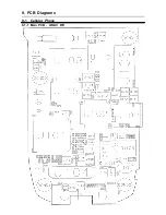
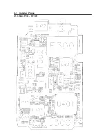
Page 84: ...9 1 Cellular Phone 9 1 1 Main PCB LOGIC B D 9 PCB Diagrams ...

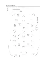
Page 85: ...9 1 Cellular Phone 9 1 2 Main PCB LOGIC B D ...

Page 86: ...9 1 Cellular Phone 9 1 3 Main PCB RF B D ...

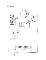
Page 87: ...9 1 4 LCD FPC ...

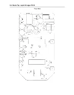
Page 88: ...9 2 Desk Top rapid Charger PCB Top View ...

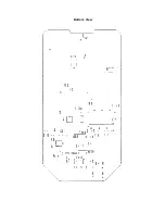
Page 89: ...Bottom View ...

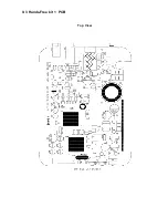
Page 90: ...9 3 Hands Free kit 1 PCB Top View ...

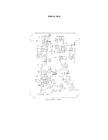
Page 91: ...Bottom View ...

Page 92: ...9 4 Cradle 1 PCB Top View ...

Page 93: ...9 5 TC PCB Top View Bottom View ...

Page 94: ...9 6 CLC PCB Top View Bottom View ...

Page 95: ...56K BITS FLASH MEMORY 8M FLASH COMBINATION MEMORY 8M FLASH 2M SRAM LCD KEY PCM CODEC I Q I Q IF AGC AMP IF AGC AMP IF BPF MIC SPK BATTERY 550mAh 1000mAh 1600mAh Regulator Regulator Regulator Regulator DC DC CONV 3 6V 3 3VT 3 3BBA 3 3AV 3 3V SCH 811 BLOCK DIAGRAM 824 894 MHz 869 894 MHz 130 38 MHz 85 38 MHz 3 7V RF SAW FILTER 2nd RF SAW FILTER 1st RF SAW FILTER Driver Amp Regulator 3 3VRC EVRC EXT ...

Page 96: ...Input Filter FET S W FET S W LED Display Rectifier Flate Reference Snubber C C C V Control C C C V Control Switch Controller O C P O V P u com Thermal protection Over voltage protection LED controller charging control Feedback Front out 4 2V 0 8A Rear out 4 2V 0 4A Buck Converter Filter ...

Page 97: ...28V POWER CONTROL STABILITY CIRCUIT REGULATOR 5V RESET CIRCUIT DC DC REGULATOR CURRENT DETECTOR VOLTAGE CURRENT FEEDBACK CRADLE IGNITION MICOM DSP CODEC VOLUME CONTROL DATA COMMUNICATION Tx AMP Rx AMP AUDIO AMP SPEAKER MICROPHONE EEPROM CALIBRATION ...

Page 98: ...10 4 Travel Charger Block Diagram ...

Page 99: ...N C131 100U 6 3V B C134 0 1uF 3 3V R137 100 SEND C185 0 01uF 100K R146 0 1uF C126 0 1uF C115 47P C205 10U 6 3V R C110 SI9161 U105 4 COMP COSC 11 DMAX_SS 3 DR 15 14 DS ENABLE 9 FB 5 8 GND 2 LL_ 6 NI PGND 13 10 D123 ROSC 12 UVLOSET VDD 1 VREF 7 16 VS 100pF C121 C106 100pF D129 SMS05C 1 2 3 4 5 6 R123 10K 1 C181 0 R110 43K 3 5 R153 150K D124 D121 3 3V 0 01uF C184 U114 TC7W04FU B B 100 R188 R142 68K 1...

Page 100: ... 470P 100 R321 L315 470N X LMX2332L U306 10 CLK 11 DATA 2 EN 12 FOLD 9 3 GND1 6 GND2 8 GND3 GND4 13 16 GND5 15 IFIN 4 RX_IN TCXO_IN 7 19 VCC VCC1 20 VP 1 18 VP1 _IFIN 14 _RX_IN 5 L314 OPEN X C324 3P U303 RF2617 DOIF 17 DO_RF 1 CDIF 4 FMIF 16 GC 3 GND1 GND2 6 11 GND3 GND4 12 10 IFCON 7 IN_SEl 8 NC 13 VCC1 14 VCC2 VCC3 15 2 _CDIF 5 _FMIF 9 _IFCON C323 1000P C327 1000P 220P 4700P C332 C329 C334 470P ...

Page 101: ...9 68P C412 1SV279 D402 C422 1000P C424 1000P VCC C417 0 1U L403 1UH X 1000P C425 C411 68P RF2628 U403 6 GND0 3 GND1 1 IF 2 IF 5 LO 4 LO_BYPASS 8 RFOUT 7 1000P OPEN C433 0 R416 R417 10K C420 0 1U L405 120N X 100P C448 C419 C428 100P C434 100P Q402 2SA1576 430K R424 R435 47K GN01037B U404 2 GND1 5 GND2 6 RF_IN 4 VAGC 1 VDD1 3 VDD2 R426 1K 120N X L404 2 OUT 6 OUTX 5 PSV 4 VCC 7 3 3VT CXA3222N U402 GC...

Page 102: ...10 5 Main Circuit Diagram 1 3 ...

Page 103: ...Main Circuit Diagram 2 3 ...

Page 104: ...Main Circuit Diagram 3 3 ...

Page 105: ...LCD FPC Circuit Diagram ...

Page 106: ...10 7 Hands Free kit 1 Circuit Diagram data ...

Page 107: ...Hands Free kit 1 Circuit Diagram audio ...

Page 108: ...Car Adaptor 1 Circuit Diagram ...

Page 109: ...10 8 Cradle 1 Circuit Diagram ...

Page 110: ...10 9 Travel Charger Circuit Diagram ...

Page 111: ...10 10 CLC Cigarette Lighter Charger Circuit Diagram ...

Reviews: