Alignment and adjustment
5-36
Samsung Electronics
5-3 VCR Section Adjustment
5-3-1 Preparations
1. Equipment ;
1) TV monitor.
2) 2CH oscilloscope(Over 20Mhz, Eguiped delay
mode ).
3) Frequency counter.
4) Pattern Generator(Equiped composite video out).
5) DC power supply(6V to 7V).
6) Suupplied standard tape(SP mode, Color-Bar).
7) 8mm blank tape for record(Hi8 is not available).
2. Composition of VCR section
1) Main PCB (System Control, Servo, Video, Audio,
DC/DC Converter, Camera)
2) Rear PCB
3) Function PCB (Function Menu, Function VCR)
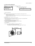
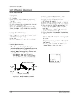
3 Pattern Generator setting ;
The pattern generator satify to the regular
specifications because VCR adjustment have to use
the composite video out of pattern generator.
Select the pattern generator to full color bar and
connect the output to oscilloscope.
-.Confirm 0.3V level of the SYNC-TIP.
-.Confirm 0.7V level of the VIDEO-SGNAL.
-.Confirm 0.3V level of the COLOR-BURST.
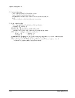
4. How to get into ÒVCR adjustment Ò mode
1) Supply power source to the camcorder.
(DC cable or DC supply)
2) Set the CAM/OFF/PLAYER switch to PLAYER.
3) Eject the cassette housing with the EJECT button.
4) Press and hold the EJECT button and the STOP
button on the FUNCTION VCR board at the
same time.
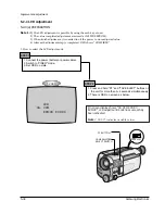
: If the OSD shows as below, VCR adjustment
mode is activated successfully.
5) Do the adjustment according to each adjustment
method.
: Release of the VCR adjustment mode is possible
by below.
-.DC power resourcing (means reattachment after
detachment.
-.Resetting of the CAM/OFF/PLAYER switch
(means reset to PLAYER after OFF).
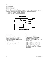
WHITE(APPROX. 100%)
1.0 0.05Vp-p
H
APPROX.
0.7V
APPROX.
0.3V
Fig. 1 Color bar signal pattern generator
0:00:00
0. EMPHA
EPR:XX EVR:XX
Summary of Contents for SCL100
Page 7: ...Product Specifications 3 4 Samsung Electronics MEMO ...
Page 21: ...Disassembly and Reassembly 4 14 Samsung Electronics MEMO ...
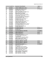
Page 67: ...Exploded View and Parts List 6 2 Samsung Electronics 6 1 Cabinet Assembly 1 ...
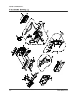
Page 69: ...Exploded View and Parts List 6 4 Samsung Electronics 6 2 Cabinet Assembly 2 ...
Page 77: ...Exploded View and Parts List 6 12 Samsung Electronics 6 6 EVF ...
Page 79: ...Exploded View and Parts List 6 14 Samsung Electronics MEMO ...
Page 105: ...Block Diagrams 8 2 Samsung Electronics 8 1 Overall Block Diagram Camera ...
Page 106: ...Block Diagrams Samsung Electronics 8 3 8 2 Overall Block Diagram VCR ...
Page 107: ...Block Diagrams 8 4 Samsung Electronics 8 3 DC DC Converter ...
Page 108: ...Block Diagrams Samsung Electronics 8 5 8 4 Drum Servo ...
Page 109: ...Block Diagrams 8 6 Samsung Electronics 8 5 Capstan Servo ...
Page 110: ...Block Diagrams Samsung Electronics 8 7 8 6 Video Playback SCL100 150 ...
Page 111: ...Block Diagrams 8 8 Samsung Electronics 8 7 Video Record SCL100 150 ...
Page 112: ...Block Diagrams Samsung Electronics 8 9 8 8 Video Playback VP L100 150 ...
Page 113: ...Block Diagrams 8 10 Samsung Electronics 8 9 Video Record VP L100 150 ...
Page 114: ...Block Diagrams Samsung Electronics 8 11 8 10 Audio ...
Page 115: ...Block Diagrams 8 12 Samsung Electronics 8 11 Camera Main ...
Page 117: ...PCB Diagrams 9 2 Samsung Electronics 9 1 Main Component Side ...
Page 118: ...PCB Diagrams Samsung Electronics 9 3 Conductor Side ...
Page 119: ...PCB Diagrams 9 4 Samsung Electronics 9 2 Rear Component Side Conductor Side ...
Page 120: ...PCB Diagrams Samsung Electronics 9 5 9 3 Function AE 9 4 Function VCR ...
Page 121: ...PCB Diagrams 9 6 Samsung Electronics 9 5 Function Menu ...
Page 123: ...PCB Diagrams 9 8 Samsung Electronics 9 7 CCD Component Side Conductor Side ...
Page 124: ...PCB Diagrams Samsung Electronics 9 9 9 8 LCD Component Side ...
Page 125: ...PCB Diagrams 9 10 Samsung Electronics Conductor Side ...
Page 126: ...PCB Diagrams Samsung Electronics 9 11 Component Side 9 1 MAIN BLUE ...
Page 127: ...PCB Diagrams 9 12 Samsung Electronics Conductor Side 9 1 MAIN BLUE ...
Page 128: ...Samsung Electronics 10 1 10 Wiring Diagram ...
Page 131: ...Schematic Diagrams Samsung Electronics 11 3 11 1 DC DC Converter ...
Page 132: ...Schematic Diagrams 11 4 Samsung Electronics T T T T T T 1 2 3 4 5 6 11 2 System Control Servo ...
Page 133: ...Schematic Diagrams Samsung Electronics 11 5 1 2 3 4 5 6 7 8 11 3 Video ...
Page 134: ...Schematic Diagrams 11 6 Samsung Electronics 11 4 Audio ...
Page 135: ...Schematic Diagrams Samsung Electronics 11 7 11 5 Front ...
Page 136: ...Schematic Diagrams 11 8 Samsung Electronics 11 6 Function AE ...
Page 137: ...Schematic Diagrams Samsung Electronics 11 9 11 7 Function VCR ...
Page 138: ...Schematic Diagrams 11 10 Samsung Electronics 11 8 Function MENU ...
Page 139: ...Schematic Diagrams Samsung Electronics 11 11 11 9 Rear ...
Page 140: ...Schematic Diagrams 11 12 Samsung Electronics 11 10 LCD ...
Page 141: ...Schematic Diagrams Samsung Electronics 11 13 11 11 CCD 1 2 3 4 5 6 7 8 ...
Page 142: ...Schematic Diagrams 11 14 Samsung Electronics 11 12 Camera Main 3 2 1 6 7 4 5 8 ...
Page 143: ...Schematic Diagrams Samsung Electronics 11 15 11 13 EVF ...
Page 144: ...Schematic Diagrams 11 16 Samsung Electronics 11 14 Adaptor ...

