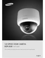
background image

English

Before installing and operating the camera, please read this user’s manual carefully.

12X SPEED DOME CAMERA 

SCP-2120


User Guide

Summary of Contents for SCP-2120

Page 1: ...English Before installing and operating the camera please read this user s manual carefully 12X SPEED DOME CAMERA SCP 2120 User Guide ...

Page 2: ...to provide reasonable protection against harmful interference when the equipment is operated in a commercial environment This equipment generates uses and can radiate radio frequency energy and if not installed and used in accordance with the instruction manual may cause harmful interference to radio communications Operation of this equipment in a residential area is likely to cause harmful interf...

Page 3: ...nstallation Example 31 Interface Symbols 34 Operating Your Camera 35 OSD Commands Function Chart and Menu Controls 35 Operating Your Camera 36 Functional Description 39 Camera Setting 39 Zoom Focus 39 White Balance 41 Exposure 42 Backlight 43 AGC 46 SSNR Samsung Super Noise Reduction 47 SSDR Samsung Super Dynamic Range 48 Day Night 49 Others 50 Sequence Setting 51 Preset 51 Swing SEQ 55 Group SEQ ...

Page 4: ...o It is useful to adjust the functions manually for detailed controls when monitoring at high zoom ratios Wide Range Auto Security Functions Multiple Preset Function Saving Up to 13 camera image properities can be saved individually to provide high quality pictures Image Holding When moving between presets in Group and Tour functions using this Preset Freeze function holds the image status and hel...

Page 5: ...ause the product to fall May cause fire Warnings May cause product malfunctions The lens is the most important component of the camera Be careful not to smear it with fingerprints This product is designed to be used indoors Outdoor use may allow water to enter the product and cause malfunctions May cause critical damage to the CCD Only use in the temperature range of between 10ºC and 50ºC to preve...

Page 6: ...and shorten its lifespan This product is designed to be used indoors When installed outdoors the camera is exposed to environmental stress such as water and high or low temperatures which may degrade video quality and or cause product malfunctions Avoid installing and operating the camera in the following places Places whose temperature exceed the camera s recommended range Places where drastic te...

Page 7: ... 5A and 250V AC 0 25A Connecting the power connector and GND incorrectly to the NC NO and COM ports may cause a short circuit and fire damaging the camera Notes Camera Wiring Interface Board RS485 Communications Camera 485 485 R RX R RX Controller or DVR Control Signal Connection Power Video Communication Signal Connection Controller Auxiliary Signal Connection Alarm Video Controller Power Supply ...

Page 8: ...he SamsungTechwin PC DVR RS 485 SVR 9416 9116 9016 Camera 485 485 PC DVR Note The following is a list of DVRs that can fully control the PTZ dome camera via RS 485 32 Channels SVR 3200 16 Channels SVR 1680 1660 1645 1650E 1640A 9416 9116 9016 9 Channels SVR 960 945 950E 940 4 Channels SVR 440 450 470 480 The following is a list of SamsungTechwin DVRs that can fully control the PTZ dome camera via ...

Page 9: ...tings 5 6 Baud Rate Settings 7 Response Mode Settings 8 Termination Settings Installing Your Camera How to Set Up Protocols and ID DIP Switches You can control various settings of the camera system using the Communication and ID DIP switches Before installing the product please set up the DIP switches according to the installation environment 1 Detach the camera frame from the install base and pla...

Page 10: ...FF OFF OFF OFF OFF 6 OFF ON ON OFF OFF OFF OFF OFF 7 ON ON ON OFF OFF OFF OFF OFF 8 OFF OFF OFF ON OFF OFF OFF OFF 9 ON OFF OFF ON OFF OFF OFF OFF 10 OFF ON OFF ON OFF OFF OFF OFF 11 ON ON OFF ON OFF OFF OFF OFF 12 OFF OFF ON ON OFF OFF OFF OFF 13 ON OFF ON ON OFF OFF OFF OFF 14 OFF ON ON ON OFF OFF OFF OFF 15 ON ON ON ON OFF OFF OFF OFF 16 OFF OFF OFF OFF ON OFF OFF OFF 17 ON OFF OFF OFF ON OFF O...

Page 11: ...FF OFF OFF ON OFF ON OFF 81 ON OFF OFF OFF ON OFF ON OFF 82 OFF ON OFF OFF ON OFF ON OFF 83 ON ON OFF OFF ON OFF ON OFF 84 OFF OFF ON OFF ON OFF ON OFF ID SW1 1 SW1 2 SW1 3 SW1 4 SW1 5 SW1 6 SW1 7 SW1 8 85 ON OFF ON OFF ON OFF ON OFF 86 OFF ON ON OFF ON OFF ON OFF 87 ON ON ON OFF ON OFF ON OFF 88 OFF OFF OFF ON ON OFF ON OFF 89 ON OFF OFF ON ON OFF ON OFF 90 OFF ON OFF ON ON OFF ON OFF 91 ON ON OF...

Page 12: ...FF ON 166 OFF ON ON OFF OFF ON OFF ON 167 ON ON ON OFF OFF ON OFF ON 168 OFF OFF OFF ON OFF ON OFF ON 169 ON OFF OFF ON OFF ON OFF ON 170 OFF ON OFF ON OFF ON OFF ON ID SW1 1 SW1 2 SW1 3 SW1 4 SW1 5 SW1 6 SW1 7 SW1 8 171 ON ON OFF ON OFF ON OFF ON 172 OFF OFF ON ON OFF ON OFF ON 173 ON OFF ON ON OFF ON OFF ON 174 OFF ON ON ON OFF ON OFF ON 175 ON ON ON ON OFF ON OFF ON 176 OFF OFF OFF OFF ON ON OF...

Page 13: ... ON ON OFF ON ON ON ON 247 ON ON ON OFF ON ON ON ON 248 OFF OFF OFF ON ON ON ON ON 249 ON OFF OFF ON ON ON ON ON 250 OFF ON OFF ON ON ON ON ON 251 ON ON OFF ON ON ON ON ON 252 OFF OFF ON ON ON ON ON ON 253 ON OFF ON ON ON ON ON ON 254 OFF ON ON ON ON ON ON ON 255 ON ON ON ON ON ON ON ON Preparing Adapter and Cables Sold Separately Distance Recommended Cable Specification 300m 4C2V RG 59 U 450m 5C2...

Page 14: ... 16 1 2 16 Coaxial Communication SVR Series Coaxial Communication SVR Series SCC 3100A CONTROLLER SUB SCC 3100A CONTROLLER MAIN CONTROL LINE VIDEO LINE CONTROL VIDEO LINE Camera Wiring Diagram RS 485 SVR Series RS 485 SVR Series The pictures below show the front view of the camera installed with a wall or flush bracket For more instructions on installing the camera please refer to the following gu...

Page 15: ...rked on the template and then drop the camera cables down through the hole 2 Mount Bracket Using the 4 screws install the mount brackets on the ceiling matching its directional guides with those of the template Installing Your Camera 3 Assemble Camera Bracket Cameras on the sides AlignTheArrow triangle corner mount bracket and the arrow shows a match to match Insert the mount bracket to the matchi...

Page 16: ...P switches for communication and ID setup are located on the bottom of the camera For more instructions please refer to Page 16 Flush Mount Type Installation Example 1 Drill Hole on the Ceiling Attach the template and then drill a hole according to the 120 mm diameter hole marked on the template Drop down the camera cables through the hole Drill another small hole for a screw to secure the camera ...

Page 17: ... communication and ID Refer to Page 16 3 Detach the Mount Housing Remove the 3 screws and then detach the mount housing from the camera Installing Your Camera 5 Install Camera Install Camera Fit the camera to the hole on the ceiling and then secure the camera using 3 Product enclosed Fixture Screws M4x20 6 Assemble Dome Cover Assemble Dome Cover Insert the grooves on the dome cover into ones on th...

Page 18: ...n Area Display Preset Edit Preset 011 1 255 Interface Symbols OSD Menu Screen Camera Setting Focus Zoom White Balance ATW Sub Menu Available Sub Menu Not Available Command Function Move the joystick up down left right Moves the OSD menus up down left right respectively Enter Focus Far Selects a menu and allows access to the sub menus ESC Focus Near Cancels a command and moves back to an upper leve...

Page 19: ...wellTime 5 7 10 15 20 30 40 60 SEC Operating Your Camera Others Sync INTERNAL LINE LOCK Line Lock Phase 0 359 ImageAdj Sharpness 1 32 Color 0 100 Freeze ON OFF Sequence Setting Preset Setting Edit Home Position Execute Clear Status Swing SEQ Pan Swing Setting Execute Clear Tilt Swing Setting Execute Clear P T Swing Setting Execute Clear Group SEQ Group1 6 Setting Execute Clear Tour SEQ Setting Exe...

Page 20: ...HOT Auto focuses the camera once after the Pan Tilt or Zoom function is used Digital Zoom Enables the maximum digital zoom Setting the digital zoom to 16X provides a total zoom of 192X 1 Zoom Focus Settings 1 1 Focus Mode and Digital Zoom Setting Menu Main Menu Camera Setting Focus Zoom Unlike the optical zoom the graphics quality of the digital zoom decreases as its zoom ratio increases The auto ...

Page 21: ... product is designed to be used indoors Installing outdoors may cause the product to malfunction OperatingTemperature about 1 700 K about 11 000 K AWC Adjusts the screen color to be optimized to the current lighting and monitor conditions Using this setting may require an readjustment if the lighting conditions changes MANUAL Enables customization of the Red and Blue gains 2 White Balance Main Men...

Page 22: ...t night or under low light conditions SENS UP LIMIT Adjusts to the maximum powered zoom per frame For optimal performance of the A FLK mode avoid using the mode in conjunction with Backlight While the Internal Sync mode is in effect setting the shutter to and facing the camera directly to a bright light source may cause poor camera performance Sens Up is disabled when the shutter is in Manual or A...

Page 23: ...m Focus White Balance ATW Exposure Back Light HLC AGC HIGH SSNR MEDIUM SSDR Day Night Others 4 3 BLC Setting Main Menu Camera Setting Back Light BLC You can selectively choose a screen area to see objects within the area more clearly than others Four direction Joystick Controls Moving the joystick in all four directions upward downward left and right adjusts the location and size of a selected are...

Page 24: ...n theAGC mode is turned off Notes SSNR significantly reduces the amount of low luminance noise OFF Disables the noise reduction function LOW Reduces only a small amount of noise but generates almost no afterimage MEDIUM The most commonly used mode Reduces a suitable amount of noise while generating a subtle afterimage HIGH Reduces noise significantly but generates obvious afterimages Camera Settin...

Page 25: ...amera to switch between the Color and B W modes Modes Auto Operates in Color mode most times and switches to B W mode if a low light level is detected during nighttime Color Operates in Color mode at all times BW Operates in B W mode at all times By using the Burst On Off sub menu burst signals can be retained or disabled Duration The camera s light sensitivity is adjustable as in the chart below ...

Page 26: ...lled using the Preset Execute command Setting Up Preset Numbers Selecting the Preset Setting menu brings up a screen as shown below Move the joystick in all four directions to select the desired number Saving Preset Locations Selecting a preset number and pressing the Enter key redirects the menu to the screen shown below Using the joystick adjust the location of the Pan andTilt functions and then...

Page 27: ...inology please refer to the section entitled Setting Up Your Camera 10 2 Preset Edit Main Menu Sequence Setting Preset Edit Sequence Setting Preset Swing SEQ Group SEQ Main Menu Camera Setting Sequence Setting Preset Edit Preset 001 1 255 Preset Edit 001 PTZ 271 045 1X Focus ONE SHOT AF Brightness 050 Iris AUTO Back Light Day Night B W Motion Det OFF Scene Adj Preset Setting Edit Home Position OFF...

Page 28: ...ng Swing SEQ The Swing function commands the camera to move between 2 selected locations monitoring the route Pan Swing Activates the Pan function for the Swing operation Tilt Swing Activates theTilt function for the Swing operation P T Swing Activates both the Pan andTilt functions for the Swing operation Swing Settings Execute Clear Settings Each of the Swing menus have sub menus with the settin...

Page 29: ...Preset Swing SEQ Group SEQ Tour SEQ PTZ Trace Auto Run Power On Resume ON Tour SEQ Setting Execute Clear 13 Tour SEQ Main Menu Sequence Setting Tour SEQ SelectingTour SEQ recalls groups of preset locations in a consecutive manner Up to 6 groups can be listed for this function Settings Selecting the Settings menu brings up the following screen Using the joystick you can enter desired group numbers ...

Page 30: ...Ack Iris Open SEC SCC 5000 OSD On Iris Open PANASONIC WV CU161C OSD ON VICON V1300X DVC Iris Open HONEYWELL HTX 3000 Iris Open AD OSD On Iris Open GE KTD 405 Iris Open BOSCH Iris Open Auto Run Mode OFF Time 30 SEC 15 Auto Run Main Menu Sequence Setting Auto Run If there is no controller operation by the user for a certain time the sequence operation designated by the user will be executed Mode Hom...

Page 31: ...roperly prior to using this option If the camera does not perform a scheduled sequencing action please reconfigure the camera time under OSD Setting Others Clock Setting Refer to Page 71 Notes Auto Run Mode SCHEDULE Time 30 SEC 17 Power On Resume and MD Dwell Time Main Menu Sequence Setting Power On Resume This is useful when the power is disconnected and reconnected due to power failures or other...

Page 32: ...ilt Limit Area Setting Area Masking Prop P T ON Digital Flip ON Image Hold OFF Jog Speed MANUAL Max Speed Level 5 Main Menu Camera Setting Sequence Setting P T Setting OSD Setting Alarm Setting Initialize Password Setting Status Main Menu Camera Setting Sequence Setting P T Setting OSD Setting Alarm Setting Initialize Password Setting Status Tilt Limit Position Activation OFF 19 Tilt Limit Main Me...

Page 33: ...cdefghijklmnopqrstuvwxyz 1234567890 BACK SPACE CLR SET Area 1 Area Name Position Activation OFF Area Setting Area 1 Area 2 Area 3 P T Setting Pan Limit Tilt Limit Area Setting Area Masking Prop P T ON Digital Flip ON Image Hold OFF Jog Speed MANUAL Max Speed Level 5 Area Masking Enter Set ESC Exit Area Masking Enter Set ESC Exit 21 Area Masking Main Menu P T Setting Area Masking If a monitoring lo...

Page 34: ...ANUAL Max Speed Level 5 23 Digital Flip Main Menu P T Setting Digital Flip Digital Flip is useful to monitor a moving object or a person passing directly under the camera When an object or a person passes directly under the camera the camera tilt monitor follows the object or person over 100 degrees to the other side of the tilt area without panning The screen inversion occurs at 100 degrees or hi...

Page 35: ...u P T Setting Jog Speed If the speed of your controller or DVR s Pant Tilt command protocol is fixed and causes slow panning and tilting you can use Manual mode MANUAL The angle of the controller handle determines the speed of Pan and Tilt the more you tilt the controller the faster the camera spins 10 60 Maintains speed regardless of the angle of the controller handle P T Setting Pan Limit Tilt L...

Page 36: ...or hides theArea Name for theArea Settings on the screen PTZ Position Displays or hides the status of the Pan Tilt and Zoom operation that is in progress Language Enables changing the system language This camera supports English Chinese French German Spanish Portuguese Korean and Italian When selecting the Camera Name and Preset Name the screen displays the Left keypad Names can be up to 12 charac...

Page 37: ... screen Date Format Changes the display format of the camera date DD MM YYYY or MM DD YYYY Set Date Enter a date Time Format Changes the display format of the camera time 24 or 12 hours Time Setup Enter a time Alarm Setting ALM MOD P SEQ NO IN1 OFF 1 OFF IN2 OFF 2 OFF 29 Alarm Setting 29 1 Setting Up Alarm Input Main Menu Alarm Setting Alarm Input Alarm Enable On Off Enables or disables theAlarm f...

Page 38: ...iption ALM MOD P SEQ NO Input 1 NO 1 Auto Pan 20 20 Input 2 NC 2 Auto Pan 20 20 Tilt Angle Speed Alarm Output Setting1 1 2 MD AUX Setting2 1 2 MD AUX Timer OFF Timer OFF OUT Off1 OUT Off2 29 2 Alarm Output Main Menu Alarm Setting Alarm Output Timer 1 2 Enables selecting anAlarm Output method On Retains an alarm output for a set duration from a minimum of 1 second to a maximum of 60 minutes upon th...

Page 39: ...ra Default Resets the camera zoom module to the Factory Default mode use if you want to reset all camera settings including Exposure and Backlight Auto Refresh Enables optimizing the status of the camera s built in electric circuits and components on a regular basis A regular operation can be scheduled This mode can be used to maintain and repair the current settings of the camera when anomalous o...

Page 40: ...otten the current password use the controller and perform Preset 255 to access the OSD without the password Upon using Factory Default Set at Main Menu Initialize the password is reset to the default 0000 Notes Status Camera Status CAM MODEL 12N CAM VERSION V1 3 DOME VERSION V1 00 COAX VERSION V1 00 CON PROTOCOL SAMSUNG TW DOME ID 001 CONTROLLER Simplex 9600 32 Status Main Menu Status Displays the...

Page 41: ...us by yourself 39 40 Use the camera s reset menu to restore the camera settings in order to default 77 Adjust Sharpness level 50 Troubleshooting Digital noise appears in picture Check if the video cable is properly connected Make sure that the power cable and video cable do not exceed the recommended maximum lengths 25 Adjust Sharpness level 50 Picture s colors are not good Check the White Balance...

Page 42: ...Day Night AUTO COLOR BW Backlight BLC HLC OFF Motion Detection ON OFF Privacy Mask ON OFF 8 Areas SSNR LOW MEDIUM HIGH OFF Sens up Auto Off Selectable limit X2 512X Gain Control Auto Off White Balance ATW ATW IN ATW OUT AWC MANUAL Product Specification The camera s position differs from the position defined in a preset This phenomenon may happen since the motors have a margin error of 0 1 Sequence...

Page 43: ...Protocol STW Pelco D Pelco P Pelco Coaxitron Panasonic Honeywell AD Vicon SEC BOSCH GE Alarm 2 In 2 Out Digtal Flip ON OFF Operating Temperature Humidity 10 C to 50 C 20 to 80 RH Storage Temperature Humidity 20 C to 60 C 20 to 95 RH InputVoltage AC24V 10 Power Consumption Max 12W External Dimensions Ø D Ø154 150mm Weight Approx 1 kg Product Specification 154mm 150mm R60 Dimension ...

Page 44: ... Name European Representative Address Equipment Type Environment Speed Dome Camera Model Name SCP 2120 Beginning Serial NO C3Z4 Year of Manufacture 2009 1 27 Conformance to EN 55022 2006 EN 50130 4 2003 We the undersigned hereby declare that the equipment specified above conforms to the above Directive s Manufacturer SAMSUNGTECHWIN CO LTD LegalRepresentativeinEurope Signature Signature Full Name B...

Page 45: ...703 TEL 82 31 740 8151 8 FAX 82 31 740 8145 SAMSUNG TECHWIN EUROPE LTD Samsung House 1000 Hillswood Drive Hillswood Business Park Chertsey Surrey UNITED KINGDOM KT16 OPS TEL 44 1932 45 5300 FAX 44 1932 45 5325 SAMSUNG TECHWIN AMERICA Inc 1480 Charles Willard St Carson CA 90746 UNITED STATES Tol Free 1 877 213 1222 FAX 1 310 632 2195 www samsungcctvusa com SALES NETWORK ...

Reviews: