background image

4-10

Samsung Electronics

Troubleshooting

NVRAM DUMP LIST

<  Device Identification  >

MFG:Xerox

CMD:LNPAP;

MODEL:Xerox WorkCenter XK Series

CLASS:Printer

DES:Xerox WorkCenter XK Series

<  Dot Count Variables  >

Black Dot Count

: 54766866

Color Cyan Dot Count 

: 84511930

Color Magenta Dot Count 

: 93785085

Color Yellow Count 

: 119673879

Total Mono Black Dot Count 

: 196564829

Total Color Cyan Dot Count 

: 236451581

Total Color Magenta Dot Count 

: 260930077

Total Color Yellow Dot Count 

: 324975620

<  Page Count Variables  >

Total Page Count 

: 122

<  Cartridge Types  >

Left Cartridge Type

: Color Standard Capacity

Right Cartridge Type

: Black Standard Capacity

<  Alignment Variables  >

Horizontal Align Value

: 16

Vertical Align Value

: 1

Quick Black Bidi Align Value 

: 4

Quick Color Bidi Align Value 

: 12

Normal Black Bidi Align Value 

: 15

Normal Color Bidi Align Value 

: 17

Note:

After downloading, you must perform the memory clearing process. Turn the printer off, and then

turn it on with the Stop button pressed and held down until the printer displays ‘memory clearing’ on
the LCD.

Summary of Contents for SCX-1000I

Page 1: ... 1000SI Manual Mult function Printer CONTENTS 1 Precautions 2 Specifications 3 Disassembly and Reassembly 4 Maintenance Troubleshooting 5 Exploded Views and Parts List 6 Electrical Parts List 7 Block Diagrams 8 PCB Diagrams 9 Schematic Diagrams ...

Page 2: ...ELECTRONICS Samsung Electronics Co Ltd August 2000 Printed in Korea VERSION NO 1 00 P N JB 0006A ...

Page 3: ... original specifications Always determine the cause of damage or overheating and correct any potential hazards 6 Observe the original lead dress especially near sharp edges AC and high voltage power supplies Always inspect for pinched out of place or frayed wiring Do not change the spacing between components and the printed circuit board 7 Product Safety Notice Some electrical and mechanical parts...

Page 4: ...revent electrostatic charge buildup in the vicinity of the assembly 3 Use only a grounded tip soldering iron to solder or desolder ESDs 4 Use only an anti static solder removal device Some solder removal devices not classified as anti static can generate electrical charges sufficient to damage ESDs 5 Do not use Freon propelled chemicals When sprayed these can generate electrical charges sufficient...

Page 5: ...er Technology Color Thermal Inkjet Engine Type 2 Pen K and CMY Operating System Windows 95 98 NT Interface IEEE 1284 ECP Support USB without HUB Mode Emulation HBP Print Speed 2 Mono 9ppm Draft 7ppm Normal Color 4 5ppm Draft 2ppm Normal Print Resolution H x V Draft 300 x 600 dpi Normal 600 x 600 dpi Best 1200 x 1200 dpi Addressable Maximum Paper Size A4 Letter Legal Effective Printing Width 8 0 20...

Page 6: ...t Optical Resolution H x V 300 x 600 dpi Interpolation Resolution Max 4800 dpi Pre scan Mode Yes 75 dpi 2 4 Ink head Mono Cartridge Color Cartridge Head Babbage 208 nozzles Birch 192 nozzles Ink type Pigment Dye Ink Color Black Color CMY Ink Yield High yield 1075 pages 200 pages 2 5 Power Supply Rated AC Input Voltage 110 240 VAC Universal Rated Input Frequency 50 60 Hz Minimum Maximum AC Input 90...

Page 7: ... Ink Cartridge Mono 1EA Color 1EA Manual 2vol 2 8 Environmental Condition Absolute Storage Temperature 5 25o C 60o C Absolute Storage Humidity 5 10 RH 90 RH Recommended Temperature 16o C 32o C Operating Condition Humidity 40 RH 70 RH 2 9 Machine Life Product Life in Time 3 Years Life Time in Pages 20 000 Printing Pages Maximum Monthly Duty Cycle 1 200 Printing Pages except Ink head Note 5 Packing ...

Page 8: ...2 4 Samsung Electronics Specification MEMO ...

Page 9: ...emoving any component from the machine note the cable routing that will be affected Whenever servicing the machine you must perform as follows 1 Check to verify that documents are not stored in memory 2 Unplug the power cord 3 Use a flat and clean surface 4 Replace only with authorized components 5 Do not force to remove or planten plastic material components 6 Make sure all components are in thei...

Page 10: ...stopper holding the scanner unit 2 Remove two screws and take out the PCB cover 4 Unplug the harness and one connector from the main PBA 3 Unlatch the harness cover by pushing on the bottom of the tabs upward then remove the cover 1 2 Unlatch the cover You should connect or remove the FPC cable vertically to avoid the FPC cable pin damage FPC cable ...

Page 11: ...Place the scanner support to its original position 3 4 Scanner 1 Before you disassemble the scanner you should remove Scanner unit assembly See page 3 3 Before you assemble or disassemble the scanner you should take on the wrist strap device for ESD protection See 1 2 ESD precausions 2 Lift and open the platen cover Planten cover ...

Page 12: ...s Disassembly and Reassembly 4 Unlatch the frame securing the scanning glass and remove it 5 Remove the glass from the main frame 6 Lift the CIS and unplug one connector from the CIS 1 2 3 Pull the cover upward and remove it ...

Page 13: ...tronics Disassembly and Reassembly 9 Remove the cover of the motor bracket 10 Remove three screws and take out the motor bracket 8 Remove the shaft 7 Remove C cap then push the part marked with A and remove the belt A ...

Page 14: ...cover to the main frame Take out the PCB cover 2 Unplug one connector from the PCB 3 Unlatch the OPE panel to the direction of the arrows and take out the cover 3 5 OPE panel 6 Remove two screws and remove the LCD board with OPE board 5 Remove six screws then turn the OPE board upside down ...

Page 15: ...Take out the cover from the main frame 3 Remove two screws securing the main PBA to the main frame and unplug all connectors Take out the main PBA 3 7 Main PBA You should connect or remove the FPC cable vertically to avoid the FPC cable pin damage 1 Before you disassemble the smart board you should remove OPE panel See page 3 6 2 Unplug one FPC cable from the PCB 3 6 Smart board ...

Page 16: ...drive PBA then pull it toward you 3 Remove one ground screw and unplug all connectors then remove the drive PBA Push the locker to unlatch the board 1 Before you disassemble the SMPS you should remove Rear cover See page 3 1 2 Unlatch the Drive PBA then pull it toward you 3 Remove one connector then remove the SMPS 3 9 SMPS Push the locker to unlatch the board ...

Page 17: ...it assembly See page 3 2 2 Remove two screws and remove the right and left side covers 3 10 Side Covers R L 1 Before you disassemble the middle cover you should remove Rear cover See page 3 1 Scanner unit assembly See page 3 2 Side covers R L See above 2 Remove three screws and remove all connectors Then take out the middle cover 3 11 Middle Cover ...

Page 18: ...2 Remove four screws securing the engine unit and unplug one connector from the drive PBA 3 Take out the engine unit from the ASF frame 1 Before you disassemble the FPC cable you should remove All covers See page 3 1 3 9 3 10 Scanner unit assembly see page 3 2 2 Unplug two FPC cables You should connect or remove the FPC cable vertically to avoid the FPC cable pin damage Samsung Electronics ...

Page 19: ...nner unit See page 3 2 Engine unit See page 3 10 2 Remove one screw securing the FPC holder to the main frame 3 Pull the part out to unlatch the FPC holder and pull the sensor actuator out then slide the FPC holder in the direction of Æ 4 Remove the FPC cable from the main frame 3 14 FPC Holder Assembly FPC holder Æ Samsung Electronics ...

Page 20: ...ble the cartridge assembly you should remove All covers See page 3 1 3 9 3 10 Scanner unit assembly see page 3 2 Engine unit See page 3 10 FPC holder assembly See page 3 11 2 Rotate to remove both springs securing the carrier shaft Then take out the carrier shaft 4 Push the holder pulley to the right and take out the belt 3 15 Cartridge Assembly ...

Page 21: ...y See page 3 2 Engine unit See page 3 10 2 Push the cartridge carrier to the direction of arrow 3 Remove the C cap 3 16 Carrier Motor 6 Push the holder pulley to the direction of arrow and remove it from the main frame 7 Unlatch the encoder by releasing both ends hooked to the main frame using a sharp tool Take out the encoder Samsung Electronics ...

Page 22: ... holder assembly See page 3 11 Cartridge assembly See page 3 12 2 Unlatch the holder by pushing the parts hooked to the main frame using a sharp tool 3 Pull the holder downward and take it out from the main frame 3 17 Roller Holder 4 Push the holder pulley and remove the belt only 5 Remove two screws securing the carrier motor and take out the motor from the main frame Samsung Electronics ...

Page 23: ...y pushing the parts hooked to the main frame using a sharp tool 3 19 Base Frame and Feed Roller 1 Before you disassemble home ass y you should remove All covers See page 3 1 3 9 3 10 Scanner unit See page 3 2 Engine unit See page 3 10 2 Unlatch the home assembly by pushing the parts hooked to the main frame using a sharp tool Take out the home assembly from the main frame 3 18 Home Ass y 3 Turn th...

Page 24: ...e 3 15 Base frame and feed roller See page 3 15 2 Remove two screws and take out the LF bracket ass y from the main frame 3 20 Line Feed Bracket Assembly 1 Before you disassemble the ASF assembly you should remove All covers See page 3 1 3 9 3 10 Scanner unit see page 3 2 Engine unit See page 3 10 2 Remove two screws and take out support SMPS from the ASF frame 3 21 ASF assembly 3 Unlatch the inne...

Page 25: ...7 Disassembly and Reassembly 4 Pull the gear out then remove the drive roller 5 Remove one screw securing the gear to the main frame and remove the gear Then take out the pick up roller Samsung Electronics ...

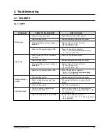
Page 26: ...or driver in Driver PBA Room light can transit a thin original Remake shading profile in the tech mode Replace U2 or U12 if it is defective U2 1 or U12 78 3 2V U2 7 or U12 79 1 9V If the CIS is defective replace it CN6 1 is 3 2V when white original copying Cn6 1 is 1 4V when idle Check the CIS harness contact Remake shading profile in the tech mode Replace U2 or U12 if it is defective U2 1 or U12 ...

Page 27: ... correct installation and use standard IEEE1284 cable Remove any other scanner driver Reboot after reinstallation of the TWAIN driver Check CN4 contact in Main PBA CN1 contact in Driver PBA whether each connection is tight If any signal level is defective replace Driver PBA U44 43 51 in Main PBA 0 8V to 2 4V TTL signal Otherwise replace Main PBA Remake shading profile in the tech mode The gap abov...

Page 28: ...the contact surfaces of ink cartridge and carriage and check if nozzles have been cleaned properly 3 Separate ink cartridge from carriage and combine them Repeat it about 5 to 6 times and check if connection is proper 4 Replace ink cartridge and check whether there s a problem with the head 5 Check if head cable is inserted well into the main circuit board and then check if nozzles have problems 6...

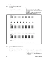
Page 29: ...kjet Solution 1 Use only transparent film designated for inkjet when you print on transparent film by an inkjet printer 2 Run Windows driver and select transparency as the kind of paper if you print on Windows 0 1 2 3 4 5 6 7 8 9 10 11 12 13 14 15 16 17 18 19 20 21 22 23 24 25 26 27 28 29 30 0 1 2 3 4 5 6 7 8 9 10 11 12 13 14 15 16 17 18 19 20 21 22 23 24 25 26 27 28 29 30 0 1 2 3 4 5 6 7 ALIGNMEN...

Page 30: ...If there is no cartridge installed install a cartridge properly Make sure that you have installed an authorized cartridge 4 2 4 Print Error PROBLEM ITEMS TO BE CHECKED HOW TO SOLVE ASF feeds paper but paper is not supplied to the engine ASF cannot feed paper Can t feed envelopes Tilted printing Check if actuator feed operates perfectly Check if paper sensor is normal Check if stopper clutch operat...

Page 31: ... 2 CON1 4 GND 12V CON1 5 GND 30V CON1 6 30V 5 The following driver ICs defect can cause power down Remove a IC and check the power on U37 U39 U25 and U26 in Main PBA U2 U3 U4 U9 and U10 in Driver PBA Download the firmware of recent version and check the system initial Check CN10 and CN14 contact in Main PBA whether each connection is tight Replace the part or OPE PBA Check the mechanical defect an...

Page 32: ...5 6 in Driver PBA whether each connection is tight If these CMOS signals are defective when the other functions normal replace the Main PBA If these 30V signals are defective when the other functions normal replace the Driver PBA Check the real jammming in paper path and remove it Check the ASF according the Paper Feed Check 5V of U12 64 when the sensor lever is interrupted and 0V of U12 64 when t...

Page 33: ... plugging the power code 4 4 2 CIS test It is used to adjust the light of CIS It is already set at CIS Test to get optimum quality WARNNING Shading profile must be made after Downloading a new Firmware If not system will not work properly When you test CIS make sure that the cover is closed 1 Press the MENU button until CIS TEST is displayed in LCD 2 Press the START button when the CIS Test operat...

Page 34: ... in the document may be printed crookedly 4 4 3 3 Clean Cartridge Allows you to clean the print nozzles on the cartridge For information on cleaning the cartridges refer to the User s Guide Note If the print is light or not clear clean the cartridge two or three times 4 4 4 NVRAM TEST 1 In the service mode press the Setup button until NVRAM TEST is displayed 2 Press the Start button and the NVRAM ...

Page 35: ...Dot Count 260930077 Total Color Yellow Dot Count 324975620 Page Count Variables Total Page Count 122 Cartridge Types Left Cartridge Type Color Standard Capacity Right Cartridge Type Black Standard Capacity Alignment Variables Horizontal Align Value 16 Vertical Align Value 1 Quick Black Bidi Align Value 4 Quick Color Bidi Align Value 12 Normal Black Bidi Align Value 15 Normal Color Bidi Align Value...

Page 36: ...ssembly Parts Lists 5 2 Scanner Assembly Scanner Assembly Parts Lists 5 3 OPE Unit Assembly OPE Unit Assembly Parts Lists 5 4 Cover Middle Assembly Cover Middle Assembly Parts Lists 5 5 Engine Assembly Engine Assembly Parts Lists 5 6 Frame ASF Assembly Frame ASF Assembly Parts Lists ...

Page 37: ...Exploded Views and Parts Lists 5 2 Samsung Electronics 5 1 Main Exploded View SAMSUNG 1 3 14 15 7 4 5 2 16 s1 9 10 13 6 12 11 8 ...

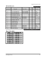
Page 38: ...PRINT HEAD MONO BIRCH 1 X 8 PRINT HEAD COLOR BIRCH 1 X 9 ELA UNIT ENGINE 1 X 10 ELA UNIT FRAME ASF 1 X 11 PMO SUPPORTER SMPS 1 X 12 SMPS FV JB44 00008A 1 O 13 ELA UNIT DRIVER JB96 01147A 1 O 14 PMO COVER SIDE RIGHT 1 X 15 PMO COVER REAR 1 X 16 PMO COVER HARNESS 1 X S1 SCREW TAPPING 6002 000175 18 O S A Service Available O Service available X Service not available BUYER ELAUNIT PANELOPE SCX 1000I X...

Page 39: ...Lists 5 4 Samsung Electronics 5 2 Scanner Exploded View SAMSUNG SAMSUNG 0 1 2 1 1 1 2 1 3 4 3 4 2 18 16 15 1 15 15 2 15 7 15 5 15 4 15 3 s1 s2 15 6 4 1 17 10 5 12 12 10 11 5 4 5 1 5 5 5 3 5 2 6 5 13 14 7 8 9 10 2 10 3 10 1 10 4 ...

Page 40: ...MO SLIDER CWBJ R JB72 00072A 1 O 8 CONTACT IMAGE SENSOR 0609 001117 1 O 9 PMO SLIDER CWBJ L JB72 00071A 1 O 10 MEA UNIT CIS CARRIAGE 1 X 10 1 PMO CARRIAGE CIS 1 X 10 2 SPRING CS CIS JB61 00004A 2 O 10 4 BELT SCANNER JB66 00007A 1 O 10 3 PMO GUIDE CARRIAGE 1 X 11 ICT SHAFT CARRIAGE 1 X 12 PMO PIVOT LOWER 2 X 13 PMO COVER SCAN LOWER JB72 00627A 1 O 14 PMO TIE STOPPER 1 X 15 MEA UNIT MOTOR BRACKET JB...

Page 41: ...Exploded Views and Parts Lists 5 6 Samsung Electronics 5 3 OPE Unit Exploded View 1 4 7 2 3 6 5 8 S1 S1 0 ...

Page 42: ... PMO KEY FUNCTION 1 X 5 PMO KEY BLACK 1 X 6 PMO CAP COLOR 1 X 7 PMO KEY SMART 1 X ONLY 1000S 8 PBA SUB OPE JB92 01096A 1 O 1000 8 PBA SUB OPE JB92 01108A 1 O 1000S S1 SCREW TAPPING 6002 000175 9 O S A Service Available O Service available X Service not available BUYER ELAUNIT PANELOPE SCX 1000I XXAA JB96 01159B SCX 1000SI XAA JB96 01144B SCX 1000SI XAC JB96 01144B SCX 1000SI XEN JB96 01144B SCX 10...

Page 43: ...Exploded Views and Parts Lists 5 8 Samsung Electronics 5 4 Cover Middle Exploded View 0 2 4 3 1 ...

Page 44: ...Parts Lists Location NO Description SEC CODE Q ty SA Remark 0 MEC COVER MIDDLE JB75 00245A 1 O 1 PMO COVER MIDDLE JB72 00617A 1 O 2 MEC SUPPORT SCANNER 1 X 3 LABEL P SHEET GUIDE 1 X 4 LABEL P WARNING 1 X S A Service Available O Service available X Service not available ...

Page 45: ... 8 S2 1 9 12 12 2 12 1 12 4 14 1 5 15 1 15 2 15 3 15 5 15 6 15 7 14 2 14 3 14 4 14 5 4 6 1 12 2 3 3 2 3 1 15 8 3 4 3 3 1 11 1 7 1 10 1 5 1 6 4 4 5 4 7 4 1 4 2 4 9 4 8 4 10 4 6 4 4 4 3 4 11 12 4 1 12 3 12 4 2 12 4 3 12 4 4 13 1 13 13 2 13 3 11 9 14 10 14 6 14 7 14 8 5 6 7 8 15 4 16 1 16 2 16 3 16 4 16 15 ...

Page 46: ...41212A 1 O 3 MEC PULLEY IDLE JB75 11110A 1 O 3 1 PMO PULLEY IDLE 1 X 3 2 ICT SHAFT PULLEY IDLE 1 X 3 3 PMO HOLDER PULLEY 1 X 3 4 SPRING CS PULLEY 1 X 4 MEC BRKT LF MOTOR JB75 00183A 1 O 4 1 MOTOR STEP LF JB31 10503A 1 O 4 2 IPR BRACKET LF MOTOR 1 X 4 3 PMO CLUTCH ARM PIN 1 X 4 4 GEAR LF IDLE75 1 X 4 5 GEAR DOUBLE 5 13 0 4 0 8 1 X 4 6 GEAR IDLE SWING12 0 8 2 X 4 7 BEARING FEED L 1 X 4 8 IPR WAVE WA...

Page 47: ...001050 1 O 13 3 CBF HARNESS PES 1 X 14 MEC FRAME HOME JB75 00174A 1 O 14 1 RPR RUBBER CAP HEAD 2 X 14 2 HOLDER CAP 2 X 14 3 SPRING CS 2 X 14 4 PMO LEVER LATCH 1 X 14 5 RPR RUBBER WIPE HEAD 1 X 14 6 PMO SLED HOME 1 X 14 7 SPRING ES LATCH 1 X 14 8 PMO FRAME HOME 1 X 15 MEL FRAME BASE JB75 00170A 1 O 15 1 MEA UNIT WHEEL STAR 6 X 15 2 PMO HOLDER WHEEL 1 X 15 3 IPR SPRING WHEEL 1 X 15 4 BELT EXIT 1 X 1...

Page 48: ...ectronics 5 13 Exploded Views and Parts Lists 0 0 5 8 8 1 8 2 8 4 8 3 8 5 8 6 8 7 7 6 14 17 15 13 16 21 2 20 18 21 3 21 4 21 21 1 27 20 9 11 22 3 22 2 22 22 1 3 4 25 23 24 2 1 26 S1 10 5 6 Frame ASF Exploded View ...

Page 49: ...TE ASF 1 X 8 2 PMO GUIDE SIDE 1 X 8 3 PMO GUIDE EXTENSION 1 X 8 4 PMO GUIDE EXTENSION DUMMY 1 X 8 5 MPR PAD FRICTION 1 X 8 6 IPR GUIDE SIDE SPRING 2 X 8 7 PMO ROLLER IDLE R 1 X 9 MEC ROLLER DRIVE JB75 00187A 1 O 10 MEC ANTISTATIC BRUSH 1 X 11 PMO GUIDE INNER 1 X 12 E RING 2 X 13 MEA UNIT PICKUP ROLLER JB97 01310A 1 O 14 PMO SHAFT PICKUP PC GF 1 X 15 PMO LEVER CASSETTE 1 X 16 SPRING LEVER LOCKING 1...

Page 50: ...2 1 X 21 3 GEAR IDLE SWING12 0 8 1 X 21 4 IPR WASHER WAVE 1 X 22 MEC GUIDE OUTER 1 X 22 1 PMO GUIDE OUTER 1 X 22 2 IPR SPRINGPINCHROLLER SPRING 3 X 22 3 PMO ROLLER PINCH 3 X 23 PMO BUCKLER FRICTION 1 X 24 PMO HOUSING BUCKLER 1 X 25 PMO GUIDE PAPER 3 X 26 CBF HARNESS CONN GND 1 X S1 SCREW TAPPING 1 X S2 SCREW TAPPING 1 X S A Service Available O Service available X Service not available ...

Page 51: ...Exploded Views and Parts Lists 5 16 Samsung Electronics MEMO ...

Page 52: ...4 3 4 1203 001037 U26 1 IC VOLTAGE REGULATOR 78L05 SOT 89 3P 185MIL PLASTIC 1404 001157 P1 P2 2 THERMISTOR PTC 2 5OHM 5 60VAC 04A 2A TP 2007 000023 R47 R133 2 R CHIP 120OHM 5 1 10W DA TP 2012 2007 000026 R15 R39 R62 R70 R171 5 R CHIP 200OHM 5 1 10W DA TP 2012 2007 000026 R56 R64 R72 3 R CHIP 200OHM 5 1 10W DA TP 2012 2007 000026 R7 R31 R3 R149 4 R CHIP 200OHM 5 1 10W DA TP 2012 2007 000026 R87 R92...

Page 53: ...7 2 R CHIP 3KOHM 5 1 10W DA TP 2012 2007 000872 R17 R21 R40 R90 R129 5 R CHIP 4 7KOHM 5 1 10W DA TP 2012 2007 000941 R104 1 R CHIP 47KOHM 5 1 10W DA TP 2012 2007 000964 R120 R121 2 R CHIP 5 1KOHM 5 1 10W DA TP 2012 2007 000964 R33 R34 R38 R61 R68 5 R CHIP 5 1KOHM 5 1 10W DA TP 2012 2007 000964 R45 R54 R55 R60 R107 5 R CHIP 5 1KOHM 5 1 10W DA TP 2012 2007 000964 R69 R80 R86 R114 R115 5 R CHIP 5 1KO...

Page 54: ...47nF 5 50V NP0 TP 2012 2203 001002 C174 C175 2 C CERAMIC CHIP 0 047nF 5 50V NP0 TP 2012 2203 001077 C86 C100 2 C CERAMIC CHIP 0 056nF 5 50V NP0 TP 2012 2203 001223 C189 1 C CERAMIC CHIP 0 82nF 10 50V X7R TP 2012 2203 001223 C74 C99 2 C CERAMIC CHIP 0 82nF 10 50V X7R TP 2012 2401 000172 C93 1 C AL 1000uF 20 35V GP TP 12 5x20mm 2402 000130 C70 1 C AL SMD 2 2uF 20 50V GP TP 4 3x4 3x5 2402 000139 C134...

Page 55: ...IC VOLTAGE COMP 393 SOP 8P 150MIL DUAL 36V CMO 1202 000170 U16 U20 2 IC VOLTAGE COMP 339 SOP 14P 150MIL QUAD 36V 1203 000623 U13 1 IC VOL DETECTOR 7045 SOT 89 3P PLASTIC 4 3 4 1203 001037 U26 1 IC VOLTAGE REGULATOR 78L05 SOT 89 3P 185MIL PLASTIC 2007 000023 R47 R133 2 R CHIP 120OHM 5 1 10W DA TP 2012 2007 000026 R3 R7 R31 R48 R65 5 R CHIP 200OHM 5 1 10W DA TP 2012 2007 000026 R39 R62 R70 R149 4 R ...

Page 56: ...2012 2007 000964 R33 R34 R38 R61 R68 5 R CHIP 5 1KOHM 5 1 10W DA TP 2012 2007 000964 R45 R54 R55 R60 R107 5 R CHIP 5 1KOHM 5 1 10W DA TP 2012 2007 000964 R69 R80 R86 R114 R115 5 R CHIP 5 1KOHM 5 1 10W DA TP 2012 2007 001001 R91 1 R CHIP 510OHM 5 1 10W DA TP 2012 2007 001041 R112 1 R CHIP 56KOHM 5 1 8W DA TP 3216 2007 001041 R118 1 R CHIP 56KOHM 5 1 8W DA TP 3216 2007 001055 R99 1 R CHIP 6 2KOHM 5 ...

Page 57: ...12 2203 000938 C56 1 C CERAMIC CHIP 0 47nF 5 50V NP0 TP 2012 2203 001002 C174 C175 2 C CERAMIC CHIP 0 047nF 5 50V NP0 TP 2012 2203 001077 C86 C100 2 C CERAMIC CHIP 0 056nF 5 50V NP0 TP 2012 2203 001223 C74 C99 2 C CERAMIC CHIP 0 82nF 10 50V X7R TP 2012 2401 000172 C93 1 C AL 1000uF 20 35V GP TP 12 5x20mm 2402 000130 C70 1 C AL SMD 2 2uF 20 50V GP TP 4 3x4 3x5 2402 000139 C134 1 C AL SMD 22uF 20 35...

Page 58: ... 3 C CERAMIC CHIP 0 022nF 5 50V NP0 TP 3216 2203 001005 C5 C6 2 C CERAMIC CHIP 0 047nF 5 50V NP0 TP 3216 2402 000176 C13 1 C AL SMD 10uF 20 16V GP TP 4 3x4 3x5 4 2802 001069 OSC1 1 RESONATOR CERAMIC 7 37MHz 0 5 TP 4 7x4 1x1 7 3301 000325 L1 1 CORE FERRITE BEAD AB 3 2x2 5x1 3mm 3404 001123 SW1 SW5 5 SWITCH TACT 12V DC 50mA 160gf 6 0x6 0x4 3mm 1 3404 001123 SW11 SW12 2 SWITCH TACT 12V DC 50mA 160gf ...

Page 59: ... 3 C CERAMIC CHIP 0 022nF 5 50V NP0 TP 3216 2203 001005 C5 C6 2 C CERAMIC CHIP 0 047nF 5 50V NP0 TP 3216 2402 000176 C13 1 C AL SMD 10uF 20 16V GP TP 4 3x4 3x5 4 2802 001069 OSC1 1 RESONATOR CERAMIC 7 37MHz 0 5 TP 4 7x4 1x1 7 3301 000325 L1 1 CORE FERRITE BEAD AB 3 2x2 5x1 3mm 3404 001123 SW1 SW5 5 SWITCH TACT 12V DC 50mA 160gf 6 0x6 0x4 3mm 1 3404 001123 SW1 SW15 5 SWITCH TACT 12V DC 50mA 160gf 6...

Page 60: ...74 R75 2 R CHIP 0 604ohm 1 1W DA TP 6331 2203 000192 C33 C38 C39 C40 C41 5 C CERAMIC CHIP 100nF 80 20 50V Y5V TP 2012 2203 000192 C42 C43 C55 C56 C57 5 C CERAMIC CHIP 100nF 80 20 50V Y5V TP 2012 2203 000192 C58 1 C CERAMIC CHIP 100nF 80 20 50V Y5V TP 2012 2203 000206 C2 C5 C63 3 C CERAMIC CHIP 100nF 10 50V X7R TP 2012 2203 000455 C25 C26 2 C CERAMIC CHIP 1nF 5 50V NP0 TP 2012 2203 000455 C2 C31 5 ...

Page 61: ...3 000192 C13 C14 C15 C16 4 C CERAMIC CHIP 100nF 80 20 50V Y5V TP 2012 2402 000176 C2 C6 2 C AL SMD 10uF 20 16V GP TP 4 3x4 3x5 4 3708 001415 CN1 1 CONNECTOR FPC FC PIC 30P 1MM SMD A SN 3709 001143 CN2 1 CONNECTOR CARD EDGE 24P 1 1mm SMD A AUF JB41 00039A 1 PCB SMIB SCX 1000 FR 4 2 LAYER 1 6 T 63 76 Samsung Electronics 6 10 6 6 SMIB PBA ONLY 1000SI SEC CODE LOCATION NO Q ty DESCRIPTION JB92 01113A ...

Page 62: ...O FF RST_O U T D R AM U 17 10 C AS R AS0 1 WR D 0 15 A 0 9 PD 0 7 ER R O R _O U T PE_O U T BU SY_O U T AC K_O U T SLC T_O U T I N I T_I N SLC TI N _I N AU TO FD _I N STB_I N 245D I R D UO _I P U 6 C DI P_XD AC K C DI P_XD REQ I P_C S R D W R D 0 15 A 0 5 C LK_O UT OPE T o D r i v e r P B A TX_I A0 TX_I A1 TX_I B0 TX_I B1 TX_PH A TX_PH B CH X CH Y U N I C O N U 21 D 0 7 A 0 5 U SB_C S R D WR U SB_I...

Page 63: ... r i dge Col um n Dr i ver U22 23 Faul t Test S Temperature Control ubst r at e Heat FAULT_TEST HO E 1 16 BA 1 13 OK2PRI NT CP 1 16 BP 1 16 PREHEAT_C CH 1 CS 1 C_HEAD_EN FAULT BI ASOFF H ead Sel ect or HSC 22 POWER CONTROL V DUO_IP U6 I M AG E PRO C ESSO R AMB_TEM P CA 1 13 HGA 1 13 PREHEAT_M HSM M _HEAD_EN CPRES MPRES BS 1 C_HEADDATA M _HEADDATA BH 1 ...

Page 64: ...t i on M odul e SRAM 2560X 8 Col or C or r ect i on M odul e I m age Pr ocessi ng M odul e SRAM 512X 32 SRAM 256x 8 D M A I F M odul e Regi st er M odul e CPU I F M odul e Vpeak Cont r ol M odul e Ver t i cal Reduct i on M odul e M ot or Cont r ol M odul e I nt er r upt Cont r ol M odul e AI N AD C_REFT ADC _REFB PI _TG PI 1 PI _RS R_LED G _LED B_LED SRAM_A 15 0 SRAM_D 7 0 SRAM_nRD SRAM_nW R A 5 0...

Page 65: ...sing LF Driver U3 TEA3718S Curre nt Sensing LF Drive r U2 TEA3718S Curre nt Sensing P1284 Port USB Port RC Filte r PWM CRA CRA LF A LFA LF B LFB SCANA SCANA SCANB S CANB LF AI0 1 LFP HA LF BI0 1 LFPHB SCANAI0 1 SCANPHA SCANBI0 1 SCANPHB CONTROL SIGNALS D0 D7 VBUS USBDM USBDP DIR RC Filte r 7 5 SMIB PBA BLOCK DIAGRAM S M C O N N E C T O R 74LVX4245 74LVX4245 CONOTRL SI GNAL D 0 7 ECC GEN KSC1623 Y ...

Page 66: ... R147 C67 U16 R64 C56 P1 C102 CN3 CN7 RA4 RA3 CN8 U8 Q10 RA2 CN4 Q12 C116 U26 LR2 U14 B10 Q11 C140 C96 70 U9 LED1 Y2 YR1 U21 CN10 40 30 20 10 1 100 CDIP1 50 60 80 C93 U23 U22 U24 U25 D5 CN5 Q13 C116 CN9 R126 CN6 KS32C6400 TP2TP1 TP3 TP5TP4 150 140 130 130 120 OCS1 120 110 110 U6 U4 140 60 70 60 70 U11 R41 CR147 DUO_IP KM68257CJ 15 BAR CODE R31 B5 B4 C59 150 100 100 200 02 21 SMD PBA C161 C159 C172...

Page 67: ... R69 R70 R62 R117 R118 R78 C79 C85 R123 LM393D U19 C83 C72 C139 R145 R164 C109 C137 R116 R162 C141 C87 C111 C122 C110 C19 C163 C165 C62 R157 C142 L1 C86 R133 C151 R195 R196 C103 C100 C89 C92 C96 C101 C97 R139 C153 C98 R173 R150 R151 R140 R132 R138 C177 C152 R152 C176 R197 R153 C107 C119 C104 C106 B8 C120 R155 C121 RR2 C108 C105 R94 C88 C84 R113 C81 R108 R129 C128 C129 R68 R16 R119 R99 C74 C99 R135...

Page 68: ...22 R100 CN3 CN5 CN7 C1 C66 U10 U9 R99 R79 R80 R58 R57 R56 R55 R54 R53 R52 R52 R19 R18 R17 R20 R16 R15 R14 R13 TEA3718S TEA3718S TEA3718S TEA3718S 4 3 1 2 CN1 CN2 B1 B2 CN8 R75 R74 U2 U3 U1 CN9 CN4 MADE IN KOREA R71 C64 U4 CN6 TEA3718S BAR CODE JB41 00040A 20000119_BBK M30 DRIVER REV 1 0 ...

Page 69: ...8 R81 LR3 L5 C54 R84 R78 C58 C32 C56 L4 1 1 4 C31 2 1 3 18 36 1 19 2 2 1 3 1 4 6 1 1 2 C27 C25 C26 C30 C28 C29 R29 R28 C40 L8 C41 C18 C52 C2 C63 Q4 R27 R26 R47 C9 R68 R30 C42 R45 R21 R31 R44 Q2 R25 DA2 ZD1 R42 R43 R46 R41 R40 R69 R23 R22 R77 R64 C43 C46 C13 C33 C45 R48 L2 L1 R60 C44 Q3 C51 C38 R67 R24 Q1 C39 C12 ...

Page 70: ... Diagram Only SCX 1000S C17 C2 U1 D1 U5 C1 C16 R5 R8 Q1 C6 C18 C5 CN1 TC7S32FU U3 C7 C9 C10 C11 U4 C8 C12 TC74LVX4245MTCX TC74LVX4245MTCX R7 C15 R12 Q3 R11 Q2 R10 R14 C13 R9 R13 C14 R6 D2 CN2 JB41 00039A M30 SMIB REV 1 O 1 22 3 20 5 18 7 16 9 14 11 12 ...

Page 71: ...al Copy Setup Enter Menu SM Print SM Scan 7 37MHz HT48R50 Stop D1 C2 D2 R3 R4 SW1 C3 C4 R8 R6 R9 SW6 SW10 SW7 SW2 J1 J2 SW8 R18 R17 D3 C9 C10 C11 R14 R15 SW11 CN2 R16 R11 R12 C5 C6 OSC1 SW3 U1 C7 C8 J3 R10 R13 SW4 C12 C13 C14 L1 SW12 5 1 SW5 SW9 R19 R21 R20 M30 OPE REV 1 1 JB41 00041A 2000 02 17 SW13 SW14 SW15 ...

Page 72: ...www s manuals com ...

Reviews: