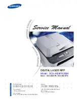
background image

Service Manual

DIGITAL LASER MFP

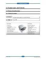
Model : SCX-4824FN/XBH

Basic : SCX-4824FN/SCX-4828FN
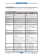
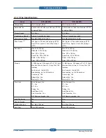
- Print/Copy Speed 
  SCX-4824FN : 24 ppm (A4) / 24 cpm (A4)
  SCX-4828FN : 28 ppm (A4) / 28 cpm (A4)

- Print resolrution 
  : 1200 dpi effective output

- CPU : 360 Mhz
- PCL5e, PCL6, IBM ProPrinter, EPSON PS(4828FN)

- Memory
  SCX-4824FN : 64MB(Max. 320MB)
  SCX-4828FN : 128MB(Max. 384MB)

- ADF : 30(4824FN) / 50(4828FN) Sheet
- MP : 1 Sheet
- Toner : 2K(Initial)/ 5K(Sales)

The keynote of Product

Summary of Contents for SCX 4828FN - Laser Multi-Function Printer

Page 1: ...4824FN 24 ppm A4 24 cpm A4 SCX 4828FN 28 ppm A4 28 cpm A4 Print resolrution 1200 dpi effective output CPU 360 Mhz PCL5e PCL6 IBM ProPrinter EPSON PS 4828FN Memory SCX 4824FN 64MB Max 320MB SCX 4828FN 128MB Max 384MB ADF 30 4824FN 50 4828FN Sheet MP 1 Sheet Toner 2K Initial 5K Sales The keynote of Product ...

Page 2: ...DE 4824 FN0XBH GSPN Global Service Partner Network North America service samsungportal com Latin America latin samsungportal com CIS cis samsungportal com Europe europe samsungportal com China china samsungportal com Asia asia samsungportal com Mideast Africa mea samsungportal com ...

Page 3: ...m Layout 2 12 QJLQH 6SHFL FDWLRQV 2 16 2 2 4 S W Descriptions 2 27 3 1 Disassembly and Reassemblyons on Disassembly 3 1 3 1 1 Screws used in the printer 3 2 3 2 General Disassembly 3 3 3 2 1 Front Cover 3 3 3 2 2 Rear Cover 3 3 3 2 3 Right Left Cover 3 4 3 2 4 Scan and ADF Assy 3 5 3 2 5 Middle Cover 3 9 3 2 6 Fuser 3 9 3 2 7 LSU 3 10 3 2 8 Main Drive Assy 3 10 3 2 9 HVPS SMPS Main board 3 11 chap...

Page 4: ... 1 Procedure of Checking the Symptoms 4 28 4 2 2 The cause and solution of Bad image 4 29 4 2 3 The cause and solution of the bad discharge 4 45 4 2 4 The cause and solution of the malfunction 4 53 4 2 5 The cause and solutions of bad environment of the software 4 62 4 2 6 Fax Phone Problems 4 66 4 2 7 Copy Problems 4 75 4 2 8 Scanning Problems 4 79 Thumbnail 5 2 5 1 Main 5 3 5 2 Cover Ass y 5 5 5...

Page 5: ...5 30 5 13 SCF 5 32 6 1 Block Diagram 6 1 6 2 Connection Diagram 6 2 7 1 Tool for Troubleshooting 7 1 7 2 Acronyms and Abbreviations 7 2 7 2 1 Acronyms 7 2 7 2 2 Service Parts 7 4 7 3 The Sample Pattern for the Test 7 8 7 4 Selecting a location 7 9 Contents chapter 6 System Diagram chapter 7 Reference Information ...

Page 6: ...reate electric shock or fire haz ards 3 Laser Safety Statement The Printer is certified in the U S to conform to the requirements of DHHS 21 CFR chapter 1 Subchapter J for Class 1 1 laser products and elsewhere it is certified as a Class I laser product con forming to the requirements of IEC 825 Class I laser products are not considered to be hazardous The laser system and printer are designed so ...

Page 7: ...tion when inserting or removing the power connector The power connector must be inserted completely otherwise a poor contact could cause overheating possibly leading to a fire When removing the power connector grip it firmly and pull 7 Take care of the power cable Do not allow it to become twisted bent sharply round corners or other wise damaged Do not place objects on top of the power cable If th...

Page 8: ...arry out the following procedures before dismantling the printer or replacing any parts 1 Check the contents of the machine memory and make a note of any user settings These will be erased if the mainboard or network card is replaced 2 Ensure that power is disconnected before servicing or replacing any electrical parts 3 Disconnect printer interface cables and power cables 4 Only use approved spar...

Page 9: ...nd weighs approximately 13 6 Kg including consumables therefore pay full attention when handling it Be sure not to hold the movable parts or units e g the control panel DADF when transporting the equipment Be sure to use a dedicated outlet with 110V 220Vpower input The equipment must be grounded for safety Select a suitable place for installation Avoid excessive heat high humidity dust vibration a...

Page 10: ...lectrical charges sufficient to damage ESDs 5 Do not use Freon propelled chemicals When sprayed these can generate electrical charges sufficient to damage ESDs 6 Do not remove a replacement ESD from its protective packaging until immediately before installing it Most replacement ESDs are packaged with all leads shorted together by conductive foam aluminum foil or a comparable conductive material 7...

Page 11: ...t Optimized Desktop MFP for Small Workgroup Target Entry SMB SCX 4824FN SSP 3ULQW 5HVROXWLRQ GGUHVVDEOH GSL 86 1 DVVHWWH 0DQXDO 7UD RS ORQH 3RVWHU RS QLWLDO 6DOHV 2SWLRQDO DVVHWWH SCX 4828FN SSP SSP WU XSOH SSP 3ULQW 5HVROXWLRQ GGUHVVDEOH GSL 86 1 DVVHWWH 0DQXDO 7UD LUHFW 86 RS ORQH 3RVWHU RS QLWLDO 6DOHV 6WDQGDUG XSOH 3ULQW 2SWLRQDO DVVHWWH ...

Page 12: ...OXGLQJ 5HG DW a HGRUD RUH a 0DQGUDNH a DQG 6X6 a 0DF 4 LQGRZV 3 6HUYHU 9LVWD ELWV LQGRZV 3 6HUYHU 9LVWD ELWV LUHG QHWZRUN 3URWRFRO 7 3 3 WKHUWDON 6103 773 7 3 3 WKHUWDON 6103 773 LUHG QHWZRUN 6XSSRUWLQJ OS LQGRZV 3 ELWV 6HUYHU 9LVWD ELWV 1HW DUH 0DF 26 a a 9DULRXV LQX 26 LQFOXGLQJ 5HG DW a HGRUD RUH a 0DQGUDNH a 6X6 a 8QL 7 7 V VWHP 9 5HO 6 3 8 5HO 5HO 6 2 68126 6SDUF RU 6RODULV LQGRZV 3 ELWV 6HUY...

Page 13: ...RPHV UVW 6 7 LIH FOH VKHHWV RU HDUV ZKLFKHYHU FRPHV UVW VKHHWV RU HDUV ZKLFKHYHU FRPHV UVW 3ULQW 6SHFL FDWLRQV Items SCX 4824FN SCX 4828FN 0HWKRG DVHU HDP 3ULQWLQJ DVHU HDP 3ULQWLQJ 6SHHG 6LPSOH 8S WR SSP 8S WR SSP 6SHHG XSOH 8S WR SSP 327 HVV WKDQ V IURP VOHHS PRGH HVV WKDQ V IURP VWDQE PRGH HVV WKDQ V IURP VOHHS PRGH HVV WKDQ V IURP VWDQE PRGH DUP XS IURP VOHHS HVV WKDQ V HVV WKDQ V 5HVROXWLRQ 8...

Page 14: ...H HV 3ODWHQ RQO 3RVWHU HV 3ODWHQ RQO 1 XS FRS XS XS ROODWLRQ RS HV XWR LW RS HV 3ODWHQ RQO VLGH RS HV 3ODWHQ RQO ORQH HV 3ODWHQ RQO 3RVWHU HV 3ODWHQ RQO XSOH RS 1 1 6FDQ 6SHFL FDWLRQV Items SCX 4824FN SCX 4828FN RPSDWLELOLW 7ZDLQ 6WDQGDUG 6WDQGDUG 7ZDLQ 6WDQGDUG 6WDQGDUG 0HWKRG RORU 6 RORU 6 6FDQ 6SHHG WKURXJK LQHDULW SSUR VHF UD SSUR VHF RORU SSUR VHF LQHDULW SSUR VHF UD SSUR VHF RORU SSUR VHF 6F...

Page 15: ... 6WDQGDUG GSL LQH GSL 6XSHU LQH GSL 3KRWR GSL RORU GSL 0D GSL 6WDQGDUG GSL LQH GSL 6XSHU LQH GSL 3KRWR GSL RORU GSL Memory 0 SSUR SDJHV DW 78 7 KDUW 0D ORFDWLRQV WR VWRUH WR URXS LDO locations D RUZDUG HV 2Q 2II URDGFDVWLQJ XS WR ORFDWLRQV RYHU SDJH HV HOD HG ID HV 0HPRU 5 HV 0 SSUR SDJHV DW 78 7 KDUW 0D ORFDWLRQV WR VWRUH WR URXS LDO locations D RUZDUG HV 2Q 2II URDGFDVWLQJ XS WR ORFDWLRQV RYHU S...

Page 16: ...OHG 3DSHU UFKLYH 3DSHU 0HGLD ZHLJKW a OE WR J a OE WR J Sensing Paper empty sensor Paper empty sensor 0DQXDO 7UD DSDFLW VKHHWV J VKHHWV J Media Sizes HWWHU HJDO ROLR 2 FLR HFXWLYH 62 6 0RQDUFK 1R HWWHU HJDO ROLR 2 FLR HFXWLYH 62 6 0RQDUFK 1R Media types 3ODLQ SDSHU 7KLFN 3DSHU 7KLQ 3DSHU 5HF FOHG 3DSHU UFKLYH 3DSHU 7UDQVSDUHQF QYHORSH DEHOV 3RVW DUG DUG VWRFN 3ODLQ SDSHU 7KLFN 3DSHU 7KLQ 3DSHU 5HF...

Page 17: ...DUWULGJH LHOG LQ DFFRUGDQFH ZLWK 62 6WDQGDUG YHUDJH DUWULGJH LHOG VWDQGDUG SDJHV LJK LHOG YHUDJH FDUWULGJH LHOG VWDQGDUG SDJHV HFODUHG FDUWULGJH LHOG LQ DFFRUGDQFH ZLWK 62 LIH HWHFW 7RQHU JDXJH VHQVRU E GRW FRXQW 7RQHU JDXJH VHQVRU E GRW FRXQW H OHFWURQLF NH 580 2QO OHFWURQLF NH 580 2QO RGH 0 T D209S MLT D209L MLT D209S MLT D209L 2 1 2 8 Consumables FRU Image Items Life Part code Transfer roller 5...

Page 18: ...XWLQJ SHUIRUPDQFH DSSOLFDWLRQ VRIWZDUH FRQQHFWLQJ PHWKRG PHGLD W SH PHGLD VL H DQG MRE FRPSOH LW RS 6SHHG LV EDVHG RQ 6LQJOH RFXPHQW 0XOWLSOH RS RQGLWLRQ 6WDQGDUG UHVROXWLRQ 005 0D LPXP PRGHP VSHHG 3KDVH E 78 7 1R KDUW 0HPRU 7 0 RQGLWLRQ 78 7 1R KDUW 6WDQGDUG 5HVROXWLRQ 3OHDVH YLVLW ZZZ VDPVXQJSULQWHU FRP WR GRZQORDG WKH ODWHVW VRIWZDUH YHUVLRQ 6RXQG 3UHVVXUH HYHO 62 0D EH DIIHFWHG E RSHUDWLQJ HQY...

Page 19: ...H VKHHWV VKHHWV VKHHWV XSOH 0RGXOH 1 Default 1 DUWULGJH 6DOHV Processor 0 0 0 Memory 0 0D 0 0 0D 0 0 0D 0 QWHUIDFH 86 7 86 7 86 7 Emulation 3 3 H 3 3 H 36 3 3 H 36 Modem Speed NESV NESV NESV Scan 5HVROXWLRQ 6FDQ GSL GSL GSL QSXW FDSDFLW VKHHWV VKHHWV VKHHWV RS RS 6SHHG 6 0 XS WR FSP 0 6 XS WR FSP 6 0 XS WR FSP 0 6 XS WR FSP FSP 86 267 1 LUHFW 86 VXSSRUW Dimension PP PP PP HLJKW J J J ...

Page 20: ...LQ FRPSRQHQW 2 2 1 Printer Components 2 2 1 1 Front View 1 Document width guides 9 Document output tray 2 ADF cover 10 USB memory port 3 Control panel 11 Paper level indicator 4 Output support 12 Optional tray 2 5 Front cover 13 Toner cartridge 6 Manual tray 14 Manual tray paper width guides 7 Tray 1 15 Scanner lid 8 Document input tray 16 Scanner glass ...

Page 21: ...l 2 11 Samsung Electronics 2 2 1 2 Rear View 1 Telephone line socket 6 Handle 2 Extension telephone socket EXT 7 Control board cover 3 USB port 8 Rear cover 4 Network port 9 Power receptacle 5 15 pin optional tray connection 10 Power switch ...

Page 22: ...ture Service Manual 2 12 Samsung Electronics 2 2 2 System Layout Engine Layout Scanner ADF Layout LSU DEVE CASSETTE DUPLEX FUSER 52 5 3 8P 52 5 29 5 23 1 29 5 23 1 52 5 6 1 833 5 6 1 833 5 6S 7 5 7 52 5 833 5 2 5 833 5 2 5 ...

Page 23: ...U SLFNXS IXQFWLRQ GULYLQJ FRQWURO IXQFWLRQ SDSHU IHHGLQJ IXQFWLRQ DQG UHPRYLQJ HOHFWURQLF VWDWLF IXQFWLRQ 4 Registration roller W KDV D SDSHU DUUDQJLQJ IXQFWLRQ SDSHU WUDQVIHUULQJ IXQFWLRQ SDSHU GHWHFWLQJ IXQFWLRQ MDP UHPRYLQJ IXQFWLRQ DQG VR RQ 5 MP tray W KDV D SDSHU DUUDQJLQJ IXQFWLRQ SDSHU WUDQVIHUULQJ IXQFWLRQ MDP UHPRYLQJ IXQFWLRQ DQG VR RQ W XVHV UXEELQJ SDG PHWKRG WR IHHG VKHHWV RI JHQHUDO...

Page 24: ...QG D SUHVVXUH UROOHU WRQHU DGKHUHV WR WKH VXUIDFH RI D SDSHU SHUPDQHQWO 4 Items for safety 3URWHFWLQJ GHYLFH IRU RYHUKHDWLQJ VW SURWHFWLRQ GHYLFH DUGZDUH FXWV RII ZKHQ RYHUKHDWHG QG SURWHFWLRQ GHYLFH 6RIWZDUH FXWV RII ZKHQ RYHUKHDWHG UG SURWHFWLRQ GHYLFH 7KHUPRVWDW FXWV RII PDLQ SRZHU Safety device IXVHU SRZHU LV FXW RII ZKHQ D IURQW FRYHU LV RSHQHG 0DLQWDLQ D WHPSHUDWXUH RI IXVHU FRYHU V VXUIDFH ...

Page 25: ...XSSO UROOHU GHYHORSLQJ UROOHU DQG EODGH RFWRU EODGH HYHORSLQJ 0HWKRG 1RQ FRQWDFWLQJ PHWKRG 7RQHU 1RQ PDJQHWLF FRPSRQHQW SXOYHUL HG W SH WRQHU 7KH OLIH VSDQ RI WRQHU RU SDJHV 6 3DWWHUQ VWDQGDUG 7RQHU UHPDLQLQJ DPRXQW GHWHFWLQJ VHQVRU HV 23 OHDQLQJ OHDQLQJ EODGH W SH 0DQDJHPHQW RI GLVXVDEOH WRQHU ROOHFW WKH WRQHU E XVLQJ OHDQLQJ ODGH 23 UXP SURWHFWLQJ 6KXWWHU 1R ODVVLI LQJ GHYLFH IRU WRQHU FDUWULGJH...

Page 26: ...SH FRQWURO XVHU FRQWURO 2Q 2II 2 VLJQDO KDQGOLQJ 6HQVRU OXWFK VLJQDO 23 6 02 0 6 FRQWURO 580 RQWURO 1 RQWURO DDR2 SDRAM DDR2 SDRAM CHORUS3 CHORUS3 EEPROM EEPROM NOR Flash NOR Flash USB 2 0 IC USB 2 0 IC Direct USB Interface Direct USB Interface Network IC Network IC USB Device Interface USB Device Interface wer part Serial Flash Serial Flash DDR2 SODIMM DDR2 SODIMM DDR2 SDRAM DDR2 SDRAM CHORUS3 CH...

Page 27: ...DQQHO WHUQDO 2 HYLFH KDQQHO 0 2 0 RQWDLQHG KDQQHOV 39 6XSSRUW LWV 0DVWHU 3 3 GGUHVVDEOH 3 6XSSRUW 3 9HUWLFDOO 3 6XSSRUW KDQQHOV 6LQJOH XDO HDP 8 57 KDQQHOV 17 55837 6XSSRUW 8S WR HGLFDWHG WHUQDO QWHUUXSWV 6XSSRUW QWHUQDO QWHUUXSWV 7 0 5 6 VWHP 7LPHUV IRU HQHUDO 3XUSRVH DWFKGRJ WLPHU 6XSSRUW 57 0 0ESV 0ESV XOO X FRPSDWLELOLW 33 RPSOLDQW 3DUDOOHO 3RUW QWHUIDFH 63 6ODYH 6HOHFW 86 86 KDQQHO RVW HYLFH ...

Page 28: ...ZLQJ VWDQGDUG LQWHUIDFHV LJK 6SHHG 86 Device LUHFW 86 6 1 RQO WKHUQHW DVH 7 ZLUHG 1 6 1 6 1 VXSSRUWV DQ LQWHUQDO 1HWZRUN QWHUIDFH WKDW FDQ EH LQVWDOOHG SUH FRQ JXUHG RQ WKH YLGHR FRQWUROOHU ERDUG DW WKH IDFWRU 7KLV VXSSRUWV DOO RI WKH PDMRU 1HWZRUN 2SHUDWLQJ 6 VWHPV VXFK DV WKH 7 3 3 HWF HWDLOV RI WKH QHWZRUN VSHFL FDWLRQ ZLOO EH SURYLGHG VHSDUDWHO RPSUHVVRU H FRPSUHVVRU RGHF DOIWRQH RPSUHVVLRQ HF...

Page 29: ...DO UHFRJQLWLRQ YROWDJH Ƒ 2XWSXW 9ROWDJH RQWURO 0HWKRG 7UDQVIHU 2XWSXW 9ROWDJH LV RXWSXWWHG DQG FRQWUROOHG E FKDQJLQJ XW RI 7 93 0 6LJQDO KDUJH 9ROWDJH 0 9 Ƒ QSXW 9ROWDJH 9 Ƒ 2XWSXW 9ROWDJH 9 a 9 Ƒ 2XWSXW 9ROWDJH 5LVLQJ 7LPH PV 0D Ƒ 2XWSXW 9ROWDJH DOOLQJ 7LPH PV 0D Ƒ 2XWSXW RQWURO 6LJQDO 0 9 3 0 38 LV 9 RXWSXW ZKHQ 3 0 LV RZ OHDQLQJ 9ROWDJH 7 9 Ƒ 9 Ƒ 7KH 7UDQVIHU 9ROWDJH LV QRW RXWSXWWHG EHFDXVH WK...

Page 30: ...P W LV DVVHPEOHG E DQ LQGHSHQGHQW PRGXOH VR LW LV SRVVLEOH WR XVH IRU FRPPRQ XVH W LV PRXQWHG DW WKH VLGH RI WKH VHW W LV FRQVLVWHG RI WKH 6036 SDUW ZKLFK VXSSOLHV WKH SRZHU IRU GULYLQJ WKH V VWHP DQG WKH KHDWHU FRQWURO SDUW ZKLFK VXSSOLHV WKH SRZHU WR IXVHU 6036 KDV WZR RXWSXW FKDQQHOV KLFK DUH 9 DQG 9 QSXW Ƒ QSXW 5DWHG 9ROWDJH 9 a 9 9 a 9 Ƒ QSXW 9ROWDJH ÀXFWXDWLQJ UDQJH 9 a 9 9 a 9 Ƒ 5DWHG UHTXH...

Page 31: ... LPXP RXWSXW Protection for loading VKRUWDJH DQG RYHUÀRZLQJ current 6KXW GRZQ 2 5 5 0A or Fuse Protection 8QGHU 36 VSHF 6KXW GRZQ a5 RU 9ROWDJH URS WULS SUNGHO CON3 Main PBA CON 24V 3 5 7 9 5V 11 13 15 CON3 Main PBA CON 24V 3 5 7 9 5V 11 13 15 CON2 Heat Lamp CON CON2 Heat Lamp CON CON1 AC POWER CON CON1 AC POWER CON F1 V2C 250V 8A V1 250V 10A F1 V2C 250V 8A V1 250V 10A F02 250V 3 15A F02 250V 3 15...

Page 32: ...W WDNHV WKH YROWDJH DQG WKH YROWDJH LV VXSSOLHG WR WKH JDWH RI 7ULDF DQG ÀRZV LQWR WKH 7ULDF V D UHVXOW WKH FXUUHQW ÀRZV LQ WKH KHDW ODPS DQG KHDW LV RFFXUUHG 2Q WKH RWKHU KDQG ZKHQ WKH VLJQDO LV RII WKH 3 LV RII WKH YROWDJH LV FXW RII DW WKH JDWH RI 7ULDF WKH 7ULDF EHFRPHV RII DQG WKHQ WKH KHDW ODPS LV WXUQHG RII 7ULDF 4 IHDWXUH 9 PRGHO 9 PRGHO 9 6 7 1 3KRWRWULDF RXSOHU 3 Ƒ 7XUQ 2Q I XUUHQW P a P...

Page 33: ...VV UUDQJHPHQW 6ROXWLRQ DQG LV URXJKO FRPSRVHG RI WZR NLQGV KLS 6ROXWLRQ 6 LVWLQJ 0RGHP KLS ZKLFK DGGV 66 6 VWHP 6LGH HYLFH IRU LQWHUIDFLQJ EHWZHHQ 6 DQG RI 0 3OXV RUH 6 8 LQH QWHUIDFH 8QLW KLS ZKLFK LV FRQWUROOHG E 66 DQG VDWLV HV HDFK 3671 5HTXLUHPHQWV E PRGXODWLQJ LQWHUQDO RQ JXUDWLRQ ZLWK FRQQHFWLQJ 7HO LQH ...

Page 34: ... UHDG 6 3L HO GDWD LQ WHUPV RI GSL LQH DQG SURFHVV UURU LIIXVLRQ OJRULWKP WH W 0L HG PRGH GLWKHU SKRWR PRGH DQG WKHQ VWRUH DWD DW 6FDQ XIIHU RQ 3 6FDQ PRGH ZLWKRXW DOJRULWKP 2Q HYHU PRGH 6KDGLQJ RUUHFWLRQ DQG DPPD RUUHFWLRQ DUH H HFXWHG DKHDG WKHQ SURFHVVLQJ LV H HFXWHG ODWHU 6FDQ PDJH RQWURO 6SHFL FDWLRQ Η 6FDQ LQH 7LPH PVHF FK Θ 6FDQ 5HVROXWLRQ 0D 3 Ι 6FDQ LGWK PP Κ main function QWHUQDO ELW KLW...

Page 35: ...H SDSHU SDVVHV WKH IHHG VHQVRU WKH SDSHU FDQQRW UHDFK WKH H LW VHQVRU DIWHU FHUWDLQ WLPH 7KH H LW VHQVRU FDQQRW EH 21 7KH SDSHU H LVWV EHWZHHQ WKH IHHG VHQVRU DQG WKH H LW VHQVRU 0 IWHU WKH WUDLOLQJ HGJH RI WKH SDSHU SDVVHV WKH IHHG VHQVRU WKH SDSHU FDQQRW SDVV WKH H LW VHQVRU DIWHU FHUWDLQ WLPH 83 0 IWHU WKH WUDLOLQJ HGJH RI WKH SDSHU SDVVHV WKH H LW VHQVRU WKH OHDGLQJ HGJH RI WKH SDSHU FDQQRW UH...

Page 36: ...HQFH 7HPSHUDWXUH RYHU VHFRQGV 3ULQWLQJ KDV EHHQ ORZHU WKDQ WKH 3ULQWLQJ 5HIHUHQFH 7HPSHUDWXUH RYHU VHFRQGV KHQ DUP8S QG 3URFHVV LW KDYH EHHQ ORZHU WKDQ WKH DUP8S 5HIHUHQFH 7HPSHUDWXUH RYHU VHFRQGV 29 5 7 5525 W KDV EHHQ KLJKHU WKDQ RYHU VHFRQGV W KDV EHHQ KLJKHU WKDQ RYHU VHFRQGV W KDV EHHQ KLJKHU WKDQ WKH 6WDQGE 5HIHUHQFH 7HPSHUDWXUH RYHU VHFRQGV 7KLV FDQ EH FKDQJHG LQ WKH IXWXUH 2 2 3 5 e LSU 7K...

Page 37: ...G ODQJXDJH ZKLFK SULQWHU FDQ XQGHUVWDQG DQG WUDQVIHUV GDWD WR VSRROHU 6WDQG DORQH SSOLFDWLRQ WKDW RIIHUV WKH YDULRXV SULQWLQJ DSSOLFDWLRQ 368 3ULQWHU 6HWWLQJV 8WLOLW 3ULQWHU 6WDWXV 0RQLWRU 1HWZRUN 0DQDJHPHQW LQ LQGRZ V VWHP HE EDVHG SSOLFDWLRQ WKDW RIIHUV WKH VDPH IXQFWLRQV DV 6WDQG DORQH SSOLFDWLRQ DQG 5 5HPRWH LDJQRVLV RQWURO LQ HE HQYLURQPHQW Firmware is made up of SSOLFDWLRQ PXODWLRQ WKDW LV D...

Page 38: ...IXQFWLRQV PDQDJHPHQW RI SULQWLQJ MRE SULQWHU DGPLQLVWUDWLRQ 6WDWXV PRQLWRU WR PRQLWRULQJ WKH SULQWHU VWDWXV E UHDO WLPH LQ HE LQGHSHQGHQW HQYLURQPHQW RQ 26 6WDQG DORQH SSOLFDWLRQ WKDW LV D VLPLODU LQGRZ VRIWZDUH DV VDPH DV DERYH 3RUW 0RQLWRU WKDW PDQDJHV WKH QHWZRUN FRPPXQLFDWLRQ EHWZHHQ VSRROHU DQG 1HWZRUN QWHUIDFH DUG RU YDULRXV DGGLWLRQDO DSSOLFDWLRQ DQG 1HWZRUN QWHUIDFH DUG WKLV LV DW UVW PDNH...

Page 39: ...HUQHO UHFHLYHV WKLV GDWD IURP RVW DQG WKHQ VHOHFW HPXODWLRQ W WR GDWD DQG VWDUW VHOHFWHG RQH IWHU HPXODWLRQ MRE HQG HUQHO VHQGV WKH RXWSXW ELW PDS GDWD WR QJLQH XVLQJ 3ULQWHU 9LGHR RQWUROOHU E FORFN W SH IRU 68 QJLQH SULQW WKH UHFHLYHG GDWD WR UHTXLUHG SDSHU ZLWK WKH VHTXHQWLDO GHYHORSLQJ SURFHVV DVH RI XVLQJ 1HWZRUN QWHUIDFH DUG IWHU XVHU VWDUW WR SULQW WKH ZDQWHG GRFXPHQW WR 3 VWULQJ RU FRPSUHVV...

Page 40: ... the machine you must perform as follows 1 Check to verify that documents are not stored in memory 2 Be sure to remove the toner cartridge before you disassemble parts 3 Unplug the power cord 4 Use a flat and clean surface 5 Replace only with authorized components 6 Do not force plastic material components 7 Make sure all components are in their proper position Releasing Plastic Latches Many of th...

Page 41: ... TAPTITE PWH B M3 L10 NI PLT SWRCH18A 3 6003 000269 ELA UNIT SCAN DRIVE SCREW TAPTITE BH S M3 L6 ZPC WHT SWRCH18A 2 6002 000440 ELA HOU FRAME SCREW TAPPING PWH 2 M3 L8 ZPC BLK SWRCH18A 13 6003 000196 SCREW TAPTITE PWH B M3 L10 NI PLT SWRCH18A 64 6003 000301 SCREW TAPTITE BH S M4 L6 ZPC WHT SWRCH18A 1 6006 001078 SCREW TAPTITE PH WSP B M3 L10 ZPC WHT SWRCH18A 1 6003 000269 ELA UNIT DRIVE SCREW TAPT...

Page 42: ... 2 Rear Cover 1 Open the front cover after take out the cassette 2 Separate the front cover from the lock the frame by pulling the front cover to the direction of arrow 1 Remove the Duplex unit 2 Open the rear cover And separate the rear cover from the locking by pulling the rear cover to the direction of arrow ...

Page 43: ...4 Samsung Electronics 3 2 3 Right Left Cover 1 Remove the one screw And pull and release the right cover somewhat 2 Release the right cover after unplug the 1 connector from Main PBA 3 Pull the left cover to the direction of arrow and release it ...

Page 44: ...F Assy 3 2 4 1 ADF Unit 1 Remove the 2 screws after remove the right cover 2 Remove the one screw and connected harness from Main board And lift the Scan Assy to the direction of arrow 1 Unplug the harness after remove the cap harness as shown below 2 Lift up and release the ADF Assy ...

Page 45: ...Disassembly and Reassembly Service Manual 3 6 Samsung Electronics 3 2 4 2 Stacker TX 1 Remove the 2 screws from the bottom of ADF Assy 2 Lift up and release the Stacker TX ...

Page 46: ...ngine unit 1 Open the ADF cover and remove it And remove the pick up roller by following below sequence 2 Remove the ADF engine unit after remove the 2 screws from the bottom of SET 3 Remove the 2 screws of the ADF cover upper And then lift it up 1 3 2 Locking 1 3 2 1 3 2 Locking ...

Page 47: ... 3 8 Samsung Electronics 3 2 4 4 OPE Unit 3 2 4 5 CIS Unit 1 Pull up the OPE unit 2 Remove the 2 connector and release the OPE unit 1 Remove the 4 screws of the Scan upper 2 Remove the 4 screw and 1 CIS cable And release the CIS unit Hook Hook ...

Page 48: ...ront and rear of the SET Unplug the harness connected to the main board And lift the middle cover up 1 Remove the rear cover Remove the Guide rear by pushing both side and removing the hinge 2 Remove the 4 screw And remove the fuser after remove the connector CAUTION The fuser is very hot So turn the printer off and wait until the printer to cool before replacing it ...

Page 49: ...ssy Before disassembly remove the cassette Cover front Cover left Cover rear 1 Release the LSU after remove the 4 screws and one connector 1 Remove the rear cover Remove the Guide rear by pushing both side and removing the hinge 2 Remove the 4 screw And remove the fuser after remove the connector ...

Page 50: ...MPS Main board Before disassembly remove the cover front cover rear cover rigth 1 Release the HVPS board after remove the 6 screws and 1 connector 2 Release the SMPS board after remove the 4 screws and 2 connector 3 Release the Main board after remove the 4 screws and all harness ...

Page 51: ...assembly Service Manual 3 12 Samsung Electronics 3 2 10 Transfer roller 1 Push HOLDER TRANSFER which holds the transfer roller and remove the roller from set Caution Be carefull not to touch the sponge of Transfer Roller ...

Page 52: ...Disassembly and Reassembly Service Manual 3 13 Samsung Electronics 3 2 11 Holder Pad unit 1 Remove the CASSETTE from SET 2 Disassemble HOLER PAD after putting out three HOOKs ...

Page 53: ...tatus and prompts during an operation 4 Status Shows the status of your machine 5 Fax Activates Fax mode 6 Copy Activates Copy mode 7 Scan Email Activates Scan mode 8 Menu Enters Menu mode and scrolls through the available menus 9 Left right arrow Scroll through the options available in the selected menu and increase or decrease values 10 OK Confirms the selection on the screen 11 Back Sends you b...

Page 54: ...utomatically Green On 7KH PDFKLQH LV SRZHUHG RQ DQG FDQ EH XVHG Blinking KHQ WKH JUHHQ VORZO EOLQNV WKH PDFKLQH LV UHFHLYLQJ GDWD IURP the computer KHQ WKH JUHHQ UDSLGO EOLQNV WKH PDFKLQH LV SULQWLQJ GDWD Red On SUREOHP KDV RFFXUUHG VXFK DV D SDSHU MDP FRYHU RSHQ RU QR SDSHU LQ the tray so that the machine cannot continue the job 7KH WRQHU FDUWULGJH LV HPSW RU QHHGV WR EH FKDQJHG Blinking PLQRU HU...

Page 55: ...g Service Manual 4 3 Samsung Electronics 4 1 3 Paper path Scanner Part Engine Part LSU DEVE CASSETTE DUPLEX FUSER 52 5 PICK UP 52 5 COVER OPEN COVER OPEN 52 5 SCAN UPPER SCAN UPPER 66 7 5 EXIT 52 5 ADF UPPER 2 5 ADF UPPER 2 5 ...

Page 56: ... 3 Rotate the bushing on the right end of the ADF roller toward the ADF 1 and remove the roller from the slot 2 Pull the document gently to the left and out of the ADF 4 Align the left end of the ADF roller with the slot and push the right end of the ADF roller into the right slot 1 Rotate the bushing on the right end of the roller toward the document input tray 2 5 Close the ADF cover Then load t...

Page 57: ... the paper from the document output tray by carefully pulling it to the right using both hands RDG WKH UHPRYHG SDJHV EDFN LQWR WKH Roller misfeed 1 Open the scanner lid 2 Seize the misfeed paper and remove the paper from the feed area by carefully pulling it to the right using both hands 3 Close the scanner lid Then load the removed pages back into the ADF ...

Page 58: ...am 2 Check Inside Inside the machine or in the fuser area Duplex Jam 0 Check Inside Inside the machine Duplex Jam 1 Open Close Door In the paper feed area or inside the machine In the paper feed area If paper is jammed in the paper feed area follow the next steps to release the jammed paper 1 Pull the tray open 2 Remove the jammed paper by gently pulling it straight out as shown below If the paper...

Page 59: ... the feeding area and if so pull it out gently and slowly RDG D SDSHU LQWR WKH PDQXDO WUD 3 Open the front cover and close it The machine will resume printing In the toner cartridge area If paper is jammed in the toner cartridge area follow the next steps to release the jammed paper 1 Open the front cover and pull the toner cartridge out 2 Remove the jammed paper by gently pulling it straight out ...

Page 60: ... Pull the guide rear on each side down and carefully take the jammed paper out of the machine Return the guide rear to its original position 4 Close the rear cover Printing automatically resumes In the duplex unit area If the duplex unit is not inserted correctly paper jam may occur Make sure that the duplex unit is inserted correctly 1 Pull the duplex unit out of the machine 2 Remove the jammed p...

Page 61: ...optional Tray follow the next steps to release the jammed paper 1 Pull the optional tray open 2 If you see the jammed paper remove the paper from the machine by gently pulling it straight out as shown below I RX FDQQRW QG WKH MDPPHG SDSHU RU LI WKHUH LV any resistance removing the paper stop pulling and go to step 3 3 Pull the tray half 4 Remove the jammed paper by gently pulling the paper straigh...

Page 62: ...Copy Setup Duple x Change Default Copie s Copy Colla tion Redu ce Enlar ge Darkness Origina l Type Scan Feature USB Feature Scan Size Origina l Type Resolutio n Scan Colo r Scan Form at E mail Fe ature Scan Size Origina l Type Resolutio n Scan Colo r Scan Form at Scan Setup Change Default USB Default E mail Defa ult System Setup Continued Report All Report Configura tion Supplie s Info Address Boo...

Page 63: ...of the display 3 Press the OK button to access the menu 3UHVV WKH HIW ULJKW DUURZ EXWWRQV XQWLO WKH PHQX LWHP H 0HQX 0DS RX ZDQW GLVSOD V RQ WKH ERWWRP line 3UHVV WKH 2 EXWWRQ WR FRQ UP WKH VHOHFWHG LWHP 3UHVV WKH HIW ULJKW DUURZ EXWWRQV XQWLO WKH PHQX LWHP H 3ULQW RX ZDQW GLVSOD V RQ WKH ERWWRP OLQH 7 Press the OK button to process your selection save your input or selection An asterisk appears n...

Page 64: ... press LQ VHTXHQFH DQG WKH EULHÀ GLVSOD V µ7 WKH PDFKLQH KDV HQWHUHG VHUYLFH WHFK PRGH 4 1 5 2 Setting up System in Tech Mode In service tech mode the technician can check the machine and perform various test to isolate the cause of a malfunction SCX 4824FN 4828FN 6HQG HYHO 70 HYHO Pause Time Dial Mode Modem Speed Error Rate RDS Clear All Mem Clear Counts Flash Upgrade Silence Time Switch Test Mod...

Page 65: ...s below the set value You can select the rate between 5 and 10 CLEAR ALL MEMORY The function resets the system to factory default settings This function is used to reset the system to the initial value when the product is functioning abnormally All the values are returned to the default values and all the information which was set by the user will be erased Method 6HOHFW WKH 0 025 5 DW WKH 7 02 2 ...

Page 66: ...XSJUDGH 6DYH WKH OHV LQ WKH VDPH IROGHU 2 In the DOS input as below and push the enter key Then it will be automatically upgraded 3 There are two commands for the conditions of product KHQ WKH SURGXFW LV LQ LGOH FRQGLWLRQ GRZQ URP OH KHQ WKH SURGXFW LV LQ 5HDG FRQGLWLRQ 7 02 7 6 783 6 83 5 2 FRS E URP OH OSW 4 Do not turn off the power while upgrading process 2 Remote Upgrade 7KLV LV D IXQFWLRQ WK...

Page 67: ...res all of the Copy Setup options to the factory default D 6HWXS Restores all of the Fax Setup options to the factory default D HDWXUH Cancels all of the scheduled fax jobs in the machine s memory As below item you can selectively clear information stored in your machine s memory GYDQFHG D Restores all of the Advanced Fax setting options to the factory default 6RXQG 9ROXPH Resets the sound and vol...

Page 68: ... the new password 7 02 7 6 783 127 721 5 5 6 5 6 3DVVZRUG I RX DUH WR HQDEOH WKH 5 6 V VWHP 1RWLI 7RQHU RSWLRQ VKRXOG EH 2II 3 3 Call setup Release In order to perform any RDS activity on a Customer MFP the SVC will have to setup a call to it 2Q VXFFHVVIXO FRPSOHWLRQ RI FDOO VHWXS RQH RU PRUH 5 6 IXQFWLRQV FDQ EH H HFXWHG EHIRUH FDOO UHOHDVH LV manually initiated KHQ FRQQHFWLQJ WR D GHYLFH 5 6 ZLO...

Page 69: ...KRZV 2 ROM TEST 8VH WKLV IHDWXUH WR WHVW WKH PDFKLQH 6 520 7KH UHVXOW DQG WKH VRIWZDUH YHUVLRQ DSSHDU LQ WKH GLVSOD 6 9 5 9 1 1 9 5 9 PATTERN TEST Using this pattern printout you can check if the printer mechanism is functioning properly It is needed in the production progress Service person doesn t need to use it SHADING TEST 7KH IXQFWLRQ LV WR JHW WKH RSWLPXP VFDQ TXDOLW E WKH VSHFL F FKDUDFWHU ...

Page 70: ...oup 3 T 30 protocol during the most recent sending or receiving operation Use this list to check for send and receive errors If a communication error occurs while the PDFKLQH LV LQ 7 PRGH WKH SURWRFRO OLVW ZLOO SULQW DXWRPDWLFDOO OTHER ITEM This list provides a list of the user system data settings and tech mode settings RQ JXUDWLRQ UHSRUW ...

Page 71: ...Alignment Troubleshooting Service Manual 4 19 Samsung Electronics supplies information report ...

Page 72: ...stem f w and diagnose printer s each function Ŷ 0HWKRG WR HQWHU IWHU WXUQ RQ WKH V VWHP SRZHU FKHFN WKH 5HDG PHVVDJH RQ WKH 2 To enter the EDC Mode Push the button like next time 0HQX ĺ 6WRS ĺ HIW DUURZ ĺ DFN ĺ 2 ĺ 5LJKW DUURZ 7KH PHVVDJH 20321 17 7 67 3UHVV 0HQX H GLVSOD RQ WKH 7R JHW RXW RI WKH 0RGH 3UHVV WKH 6WRS NH ...

Page 73: ...G PRWRU ZLOO EH VORZO UXQ 0DLQ PRWRU ZLOO DXWR VWRS DIWHU VHFRQGV DQG 2 PHVVDJH ZLOO EH displayed 3 Fan Test Item Description Fuser Fan I 2 NH LV SXVKHG DIWHU 21 GLVSOD HG IDQ ZLOO EH UXQ XVHU IDQ ZLOO DXWR VWRS DIWHU VHFRQGV DQG 2 PHVVDJH ZLOO EH GLVSOD HG SMPS Fan I 2 NH LV SXVKHG DIWHU 21 GLVSOD HG IDQ ZLOO EH UXQ 6036 IDQ ZLOO DXWR VWRS DIWHU VHFRQGV DQG 2 PHVVDJH ZLOO EH GLVSOD HG 68 DQ I 2 N...

Page 74: ...OO EH GLVSOD HG 68 5HDG I 2 NH LV SXVKHG DIWHU 21 GLVSOD HG PRWRU ZLOO EH UXQ PHVVDJH will be displayed V QF I 2 NH LV SXVKHG DIWHU 21 GLVSOD HG PRWRU ZLOO EH UXQ PHVVDJH will be displayed 7 DEV Control Item Description 7 9 I 2 NH LV SXVKHG DIWHU 21 GLVSOD HG 7 9 ZLOO EH WXUQHG RQ 7 9 I 2 NH LV SXVKHG DIWHU 21 GLVSOD HG 7 9 ZLOO EH WXUQHG RQ Dev Bias I 2 NH LV SXVKHG DIWHU 21 GLVSOD HG HY LDV ZLOO...

Page 75: ...age 1 OPC Drum 75 5mm KLWH VSRW ORFN 6SRWV 2 Charge Roller 26 7mm Block Spot and Periodic Band 3 Supply Roller 47 1mm Periodic Band by little difference of density 4 Developing Roller 35 2mm KLWH 6SRW RUL RQWDO EODFN EDQG 5 Transfer Roller 47mm Ghost Damaged Image by abnormal transfer 6 HDW 5ROOHU 77 8mm Black Spots or Vertical Black Band 7 1 3UHVVXUH 5ROOHU B VW 62 8mm Blackground 7 2 3UHVVXUH 5R...

Page 76: ...ng fax machine has not answered after several redial attempts Try again Make sure that the receiving machine is operational Stop Pressed Stop Clear has been pressed during an operation Try again yyy Paper Empty There is no paper in the tray RDG SDSHU LQ WKH WUD yyy Paper Mismatch 7KH SDSHU VL H VSHFL HG LQ WKH SULQWHU properties does not match the paper you are loading RDG WKH FRUUHFW SDSHU LQ WKH...

Page 77: ...ial a number manually using the number keypad Install Toner The toner cartridge is not installed Install the toner cartridge Invalid Toner The toner cartridge you have installed is not for your machine Install the a Samsunggenuine toner cartridge designed for your machine 3 RQÀLFW The network IP address you have set is being used by someone else Check the IP address and reset it if necessary Line ...

Page 78: ... area Clear the jam Replace Toner This message appears between Toner PSW DQG 7RQHU RZ VWDWXV Replace the toner cartridge with a new one Retry Redial 7KH PDFKLQH LV ZDLWLQJ IRU D VSHFL HG time interval to redial a previously busy station You can press OK to immediately redial or Stop Clear to cancel the redial operation Scanner locked The scanner module is locked Unlock the scanner and press Stop C...

Page 79: ... work as Stop is selected Replace the toner cartridge with a new one Toner Exhausted The lifespan of the toner cartridge which the arrow indicates is reached This message appears when the toner is completely empty and your machine stops printing Replace the corresponding toner cartridge with a Samsunggenuine cartridge Toner Low The corresponding toner cartridge is almost empty Take out the toner c...

Page 80: ...mptoms HIRUH DWWHPSWLQJ WR UHSDLU WKH SULQWHU UVW REWDLQ D GHWDLOHG GHVFULSWLRQ RI WKH SUREOHP IURP WKH FXVWRPHU Power On UURU 21 Ready or Power save Test Print printing Quality is 1RPDO Refer to Solution of Image Problem Refer to 6WDWXV Error Message END No Power Power Module error Main PBA error Panel PBA error UHHQ RQ ...

Page 81: ...nting 3 Partly depression or deformation on the surface of the transfer roller 2 Scratched surface of the charge roller in the toner cartridge 1 Damaged develop roller in the Toner cartridge Deformed Doctor blade or cleaning blade If causes 1 and 2 occur in the toner cartridge replace the toner cartridge and try to print out Replace the transfer roller if occurred as No 3 Digital Printer Digital P...

Page 82: ...and blade In case the life of the toner cartridge has been expired white lines or light image occur in front of the image 1 Foreign matter stuck onto the window of internal lenses RI 68 PLUURU Foreign matter stuck onto the ZLQGRZ OHDQ WKH 68 ZLQGRZ with recommended cleaner IPA Clean the window with a clean cotton swab Replace the toner cartridge No 3 Remove the foreign matter and burr of the expos...

Page 83: ...6 7mm Supply roller 47 1mm Develop roller 35 2mm Transfer roller 47mm 1 Bad contacts of the voltage terminals to toner cartridge Clean each voltage terminal of the Charge Supply Develop and Transfer roller remove the toner particles and paper particles 1 Clean the right Gear that has relatively small gap of the teeth in the OPC 2 If the malfunction persists replace the toner cartridge Digital Prin...

Page 84: ...m interval 1 If dark or blurry black spots occur periodically the rollers in the Toner cartridge may be contaminated with foreign matter or paper particles Charge roller 26 7 mm interval OPC drum 75 5 mm interval Run OPC cleaning Mode Print and run the Self test 2 or 3 times In case of 75 5 mm interval unremovable in 1 cleanly remove foreign substances stuck on the OPC location equivalent to black...

Page 85: ...igh voltage terminal in WKH 936 DQG WKH RQH in the set 4 Abnormal output IURP WKH 936 5XQ VHOI WHVW DQG FKHFN a Check if the Toner Save mode is off Check if the density is light No 1 Replace the toner cartridge and try to print out 1R ait 30 minutes after printer is powered on before you start printing No3 Clean up the contaminated area by the toner 5HSODFH WKH 936 LI WKH problems are not solved b...

Page 86: ...side of the Toner cartridge and charge terminal RI 936 3 VD0 signal of the Main PBA LV RZ VWDWH 1 No charge voltage in the engine board Check the state of the connector which connects the engine board DQG 936 1 Clean the high voltage charge terminal 5HSODFH WKH 936 LI QRW VROYHG by the above direction 1 and 2 5HSODFH WKH 68 8QLW RU 0DLQ 3 Digital Printer Digital Printer Digital Printer Digital Pri...

Page 87: ...ad blade 2 The life of the Toner cartridge has expired 1 The pressure force on the left and right springs of the transfer roller is not even the springs are damaged the transfer roller is improperly installed or the transfer roller bushing or holder is damaged Replace both the left and right 6SULQJ ROGHU Occur in the toner cartridge gently shake the toner cartridge Replace the toner cartridge and ...

Page 88: ...er a page and hasnÕt it been XVHG ORQJ WLPH The toner cartridge is basically designed to print 7K sheets with 5 image If it prints more than 8K sheets with 2 coverage a background can occur Replace the toner cartridge when the life span of it has been ended The A S is not guaranteed if using a recyled the toner cartridger 1 If the problem is still not solved replace the toner cartridge 2 Gently sh...

Page 89: ...es between high voltage terminal in the main body and the one in the 936 ERDUG 3 The life of toner cartridge is expired 4 Transfer roller lifetime 50K sheets has expired Clean the terminals when contaminated by toner particles Occur in the toner cartridge replace the toner cartridge and try to print out Replace the engine board if not solved by the above directions 1 2 If not solved by the directi...

Page 90: ...8 Samsung Electronics 5 Abnormal low temperature below 10 6 Damaged cleaning blade in the toner cartridge ait about 1 hour after power on before using printer Occur in the toner cartridge replace the toner cartridge and try to print out Continue ...

Page 91: ... or transparencies using manual feeder KHQ SULQWLQJ RQ FDUG VWRFN thicker than normal paper or WUDQVSDUHQFLHV VXFK DV 2 3 higher transfer voltage is required Select Thick Mode on paper type menu from the software application and after using returning to the original mode is recommended Digital Printer Digital Printer Digital Printer Digital Printer Digital Printer Digital Printer 75 5mm ...

Page 92: ...tervals The temperature of the fuser is maintained high Disassemble the fuser and remove the contaminated toner particles on the roller and clean the foreign matter between Thermistor and HDW UROOHU Caution can be deformed Digital Printer Digital Printer Digital Printer Digital Printer Digital Printer Digital Printer 62 8 or 77 6mm ...

Page 93: ...e transfer roller is contaminated stains on the face of page will occur 1 Toner leakage due to improperly sealed toner cartridge Replace the toner cartridge If the transfer roller is contaminated run PC Cleaning Mode Print 2 or 3 times And perform Self Test 2 or 3 times to remove contamination Digital Printer Digital Printer Digital Printer Digital Printer Digital Printer ...

Page 94: ...Perform the OPC Cleaning Mode Print 2 or 3 times Run Self Test to remove the contamination of the transfer roller 1 Replace the transfer roller if contaminated severely 2 Disassemble the fuser and clean WKH 5 HDW 5ROOHU DQG 3 5 Pressure roller And check the DUHD EHWZHHQ 5 DQG Thermistor If contaminated clean the area not to be deformed Digital Printer Digital Printer Digital Printer Digital Printe...

Page 95: ...cription Blank page is printed Bad ground contacts in OPC and or toner cartridge 1 Check if the Ground OPC is defective set inside right side 2 Remove contamination of the terminals of the toner cartridge and the unit Digital Printer Digital Printer Digital Printer Digital Printer Digital Printer ...

Page 96: ...er turns on several blank pages print 1 Bad ground contacts in OPC and or toner cartridge Remove contamination of the terminals of the toner cartridge 2 Abnormal solenoid 1 Perform the engine self test using EDC Mode to check if the Solenoid is normal 2 If not solved by the above directions 1 2 Replace the engine board 3 Turn the power off delete the data of PC and try printing again ...

Page 97: ... 45 Samsung Electronics 4 2 3 The cause and solution of the bad discharge 1 Wrong Print Position Description Printing begins at wrong position on the paper rong sense time caused by defective feed sensor actuator Replace the defective actuator ...

Page 98: ... whether the assembly slot between shaft pickup and housing pickup opens or is broken away 5 If the paper feeds into the printer and Jam 0 occurs perform EDC Mode to check feed sensor of the engine board 1 Check the Solenoid by using EDC Mode 2 Check if the pad is loose due to bad sealing of the side pad Replace the solenoid Clean with soft cloth dampened with IPA Isopropyl Alcohol or water Replac...

Page 99: ... in the fuser just after passing through the Actuator Feed 1 If the recording paper is jammed in front of or inside the fuser 2 If the recording paper is stuck in the discharge roller and the fuser just after passing through the Actuator Feed Feed Actuator may be defective Replace the SMPS or Exit Sensor 1 Replace the Main PBA 2 Reassemble the Actuator Feed and Spring Actuator if the movement is b...

Page 100: ...n away or transformed It occurs when the Spring of a Guide claw is broken away or transformed W RFFXUV ZKHQ WKH HDW 5ROOHU RU Pressure Roller is seriously contaminated with the toner Check if the exit sensor actuator is defective Check if the actuator exit is deformed Check if the lever part is deformed in shape Check whether burrs occur in the assembly part of the actuator exit or not and if the ...

Page 101: ...ront or inside a duplex module 2 It is a case that a paper cannot reach to a registration sensor 1 A case that a paper jam occurs on A after it is reversed replace a 2nd exit roller after checking its operation 2 A case that a paper jam occurs on B after it is reversed replace a duplex roller after checking its operation ...

Page 102: ...GH Rear in the Cassette if the position is correct Replace the solenoid if necessary 2 Solenoid malfunction the solenoid does not work properly Perform EDC Mode Replace the Main PBA 3 Pad Friction is contaminated with foreign matter oil Clean the pad friction with soft cloth dampened with IPA Isopropyl Alcohol 4 The face of paper is blended Use the smooth paper ...

Page 103: ...If set After disassembling the fuser clean contamination between the heat roller and the thermostor and remove the contamination of the pressure roller 2 Check the claw of the fuser whether it is deformed 1 If there is heavy background repair it by the background troubleshooting method 2 Clean the surface of the heat roller with IPA or water 3 Check the warp or separation of the print claw and the...

Page 104: ...ption Paper is rolled up in the OPC RZ WR UHPRYH WKH UROOHG SDSHU in the OPC Remove the paper while turning the OPC against the ongoing direction Clean fingerprints on the OPC softly with soft cloth dampened with tissue 1 Paper is too much thin Recommend to use normal paper 2 The face of paper is curled ...

Page 105: ... whether a thermostat AC wire and heat lamp are open or not Replace the fuser if a thermostat is open Replace the fuser if a thermistor sensor is located deep inside of a sponge Check whether the overheat mode circuit operates normally or not Replace the fuser 2 Check whether a thermistor is open or not HDW ODPS 21 2 WHVW 4 It could not operate due to a gear of a fuser is melted ...

Page 106: ...tronics 2 LSU Error Description PMOTOR ERROR HSYNC ERROR KHFN ZKHWKHU WKH 68 connector is disconnected or not 5HSODFH D 68 Replace a main board if the same error occurs again after replacing D 68 KHFN ZKHWKHU WKH 68 motor is rotating or not KHFN WKH 6 1 VLJQDO ...

Page 107: ...al 4 55 Samsung Electronics 3 Not function of the gear of the fuser due to melting away Description The motor breaks away from its place due to gear melting away KHFN WKH HDW DPS 1 Replace the Fuser 2 Replace the Main PBA 3 Replace the SMPS ...

Page 108: ... Description Paper empty error message is displayed on LCD when paper is loaded in the cassette 1 Bending or deformation of the actuator of the paper sensor Replace the defective actuator Replace the Sensor PBA 2 The function of the engine board is defective 3 Check the Connector ...

Page 109: ...mpty without indication Description Paper empty error message does not display when the paper cassette is empty 1 Bending or deformation of the actuator of the paper sensor Replace the defective actuator Replace the engine board 2 The function of the engine board is defective ...

Page 110: ...hen the print cover is closed 1 The hook lever in the front cover or Guide rear may be defective Replace the hook lever if defective 1 Check the insertion of the RYHU 2SHQ 6 RQQHFW 2 Replace the Main Control ERDUG RU RYHU 2SHQ 6 2 Check the connector and circuit of the cover switch department in the Main Control board ...

Page 111: ...ver is open Description The Error LED does not come on even when the printer cover is open 1 Check the connector and circuit of the cover switch department in the Main Control board Perform EDC test 1 Check the insertion of the RYHU 2SHQ 6 RQQHFW 2 Replace the Main Control ERDUG RU RYHU 2SHQ 6 ...

Page 112: ...ned on all lamps on the operator panel do not come on 1 Check if the power input and SMPS output are normal Replace the power supply cord or SMPS 1 Replace the control board 2 Replace the OP panel 2 Check the inferiority RI 3DQHO RU ZLQGRZ RQ WKH front cover if the OP panel does not appear after normal warming up ...

Page 113: ...Line Getting Curved Description When printing vertical line gets curved I WKH VXSSO RI Y LV unstable in the Main Control board OLQNLQJ ZLWK 68 FKHFN GULYH E EDC Mode 68 KHFN 5HSODFH 68 1 Replace theToner Joint PBA 2 Replace the MainPBA 2 Chect the Deve PBA in the Toner Cartridge ...

Page 114: ...ort is proper If you use windows check if the printer driver in the controller is set up If the printer driver is properly set up check in which program the printing is not working The best way to find out is to open the memo pad to check the function of printing If it is not working in a certain program adjust the setup the program requires Sometimes WKH SULQWRXW LV QRUPDO ZLWKLQ WKH LQGRZV EDVLF...

Page 115: ...inter port is not proper Check if the connection is properly done and if the parallel port in CMOS is rightly set up As a printer port Select ECP or SPP among SPP Normal ECP and EPP modes increase printing speed SPP normal mode support 8 bit data transfer while ECP Mode transfer the 12 bit data If the regular font is not printing the cable or the printer driver may be defective Turn the PC and pri...

Page 116: ...port in the CMOS SETUP Select SPP Normal or ECP 37 Port the among ECP EPP or SPP in the CMOS Setup Check the printer in My Computer to see if the printer driver is compatible to the present driver or delete the old driver if defective and reinstall the new driver Delete the unnecessary files to secure enough space of the hard disk and start printing job again 2 Printer Driver Error 3 Error message...

Page 117: ...rams except the current one if possible KHQ H SHFWHG WR FROOLGH with other program Delete the printer driver completely and reinstall it KHQ DQ DSSOLFDWLRQ program or the printer driver is damaged After rebooting the computer check for viruses restore the damaged files and reinstall the program to do the printing job KHQ VRPH ILOHV UHODWHG WR OS are damaged or virus infected Add up enough memory t...

Page 118: ... 7 1 FRUUHFWO If the telephone cord is normal but there is no dial tone then try to UHSODFH WKH 8 G I RX FDQQRW KHDU WKH 2 VRXQG WKH 23 Ass y may be defective Try to replace the OPE Ass y KHFN LI LW PDNHV VRXQG ZKLOH 2 NH LV SUHVVHG 3 Check the connection of 51 66 EHWZHHQ WKH 8 DQG WKH 0DLQ G Check the Speaker connection and try to replace it DVWO try to replace the Main B d 4 Check if the SPEAKER...

Page 119: ...VRXQG WKH 23 Ass y may be defective Try to replace the OPE Ass y I RX FDQ FDWFK D VRXQG after checking the connection of 51 66 EHWZHHQ WKH 8 DQG the Main PBA try to replace the 51 66 LOH WKH 877ON KEY is pressed check to catch D VRXQG 3 Check the connection of 51 66 EHWZHHQ WKH 8 DQG WKH 0DLQ 3 The problem still persists then UHSODFH WKH 8 DQG WKH PDLQ G in sequence Notes Product supports the MF t...

Page 120: ...he FAX FORWARD RECEIVE is not functioning 1 Check if you can catch a dial tone by pressing 2 If the MODEM testing is normal and there is no dial tone then try WR UHSODFH WKH 8 G If the MODEM testing is abnormal try to replace the Main B d 2 Check if you can catch a RECEIVE tone while MODEM testing in the 7 0RGH ...

Page 121: ...eceived data are broken 1 Check if there is NOISE when pressing on hook dial If it makes NOISE while using on hook dial replace or repair the telephone line 2 Check the RECEIVE condition by trying to forward a FAX to another fax machine from the forwarding side FAX 3 Check if the telephone line connected to the Product is contaminated or gets stripped off or down ...

Page 122: ...ription FORWARD is functioning but RECEIVE is not functioning or the received data are broken 1 Check if there is NOISE when pressing on hook dial If it makes NOISE while on hooking replace or repair the telephone line 2 Check the RECEIVE condition by trying to receive a FAX at another fax machine ...

Page 123: ...thened or cut in the printing 1 Check if there is NOISE when pressing on hook dial If it makes NOISE rearrange the telephone line Refer to Defective FAX RECEIVE Check if the FAX status of the forwarding side is also normal 2 Ask to the forwarding side check the image quality of another machine receiving a FAX additionally sent to ...

Page 124: ...nics 7 Defective FAX RECEIVE 3 Description The phone is ringing continuously but it cannot receive Check if the RECEIVE Mode is 7 MODE or FAX MODE Even when the RECEIVE Mode is changed to FAX MODE it cannot UHFHLYH WKHQ UHSODFH WKH 8 DQG the Main B d in sequence ...

Page 125: ...Samsung Electronics 8 Defective FAX RECEIVE 4 Description The received data is reduced by more than 50 in the printing Check the FAX status of the forwarding side After checking the data of the forwarding side correct the FAX of the forwarding side ...

Page 126: ...ription The automatic receiving function is not working 1 Check if the RECEIVE Mode is 7 MODE or FAX MODE 1 If the RECEIVE Mode is set to the 7 MODE reset it to the FAX MODE 2 Even after the RECEIVE Mode is changed to the FAX Mode it cannot receive then try to UHSODFH WKH 8 DQG WKH 0DLQ B d in sequence ...

Page 127: ...ck Copy Description Black page is printed out when copy 1 Check the Scan Cover open Room light ca transit a thin original Remake shading profile in the tech mode 2 Check shading profile 3 Check white black reference voltage in Main PBA Replace U60 if it is defective U60 154 0 5V U60 155 3 3V ...

Page 128: ...ervice Manual 4 76 Samsung Electronics 2 White Copy Description White page is printed out when Copy 1 Check the CIS problem in Main PBA Check the CIS harness contact Remake shading profile in the tech mode 2 Check shading profile ...

Page 129: ...y 1 Check the Scanner Motor and any mechanical disturbance Check the right position of the Scanner Motor and check the any mechanical disturbance in the CIS carriage part If any driver is defective replace it Connection PBA U4 1 19 or U5 1 19 0V to 24V swing signal when operating 2 Check the Motor Driver in Driver PBA ...

Page 130: ...ive Image Quality Description The copied image is light or bad 1 Check shading profile Remake shading profile in the tech mode The gap above 0 5 mm can cause a blurred image 2 Check the gap between original and scanner glass See Print troubleshooting 3 Check printing quality ...

Page 131: ...he PC and the cable are not connected properly reconnect it After confirming that it is proper by performing a PC printing test related to driver setup if it is not so reinstall it Refer to User s Manual 2 Check if the driver is installed properly If copy function works replace the Main PBA If copy function doesn t work replace the CIS Ass y and try again 3 Check if copy function operates normally...

Page 132: ...PC scanned is not clear or bad 1 Check the waveform form by performing a CIS test in 7 0RGH If the CIS waveform form is abnormal try to replace the CIS Ass y If the resolution is set to low let the user be acquainted with the using method well 2 Check if the resolution is set too low in PC Scan options Refer to User s Manual ...

Page 133: ...10 Duplex Unit 5 25 5 11 Fuser 5 27 5 12 Cassette 5 30 5 13 SCF 5 32 5 ExplodedView and Parts Contents DIGITAL LASER MFP The keynote of Product Print Copy Speed SCX 4824FN 24 ppm A4 24 cpm A4 SCX 4828FN 28 ppm A4 28 cpm A4 Print resolrution 1200 dpi effective output CPU 360 Mhz PCL5e PCL6 IBM ProPrinter EPSON PS 4828FN Memory SCX 4824FN 64MB Max 320MB SCX 4828FN 128MB Max 384MB ADF 30 4824FN 50 48...

Page 134: ...Service Manual 5 2 Samsung Electronics Thumbnail 5 1 Main 5 2 Cover Ass y 5 3 Cover Middle 5 4 Frame 5 5 Main Drive 5 6 Scan Ass y 5 7 ADF Ass y 5 8 Platen Ass y 5 9 OPE Unit 5 10 Duplex Unit 5 11 Fuser 5 12 Cassette 5 13 SCF ...

Page 135: ...ExplodedView and Parts Service Manual 5 3 Samsung Electronics 5 1 Main 6 2 1 4 17 9 10 11 8 12 7 14 15 16 18 19 25 13 3 5 21 0 20 29 23 22 ...

Page 136: ...5 1 7 JC39 00824A CBF HARNESS HVPS 1 SA 5 1 8 JC96 04731A ELA UNIT RX DRIVE 1 SA 5 1 9 JC39 00820A CBF HARNESS MOTOR SOLENOID 1 SA 5 1 10 JC39 00816A CBF HARNESS AC INLET 1 SA 5 1 11 JC66 01218A ROLLER TRANSFER 1 SA 5 1 12 JC96 04733A ELA UNIT LSU 1 SA 5 1 13 JC96 04736A MEA UNIT DUPLEX 1 SA 5 1 14 JC97 03015A MEA UNIT COVER_REAR 1 SA 5 1 15 JC96 05079B ELA HOU COVER RIGHT 1 SA 5 1 16 JC97 03221A ...

Page 137: ...ExplodedView and Parts Service Manual 5 5 Samsung Electronics 5 2 Cover Ass y 1 2 3 4 5 2 1 2 2 2 3 2 4 3 1 3 2 3 3 3 4 4 1 4 2 4 3 4 4 1 1 1 2 1 3 1 4 1 5 0 ...

Page 138: ...T 1 SNA 5 2 2 JC97 03221A MEA COVER LEFT 1 SA 5 2 2 1 JC63 01920A COVER LEFT 1 SNA 5 2 2 2 JC72 01405A SPONGE COVER SIDE L 1 SNA 5 2 2 3 JC72 01460A SPONGE SIDE BOTTOM L 1 SNA 5 2 2 4 JC72 01462A SPONGE SIDE FRONT 1 SNA 5 2 3 JC97 03015A MEA UNIT COVER_REAR 1 SA 5 2 3 1 JC63 01526A COVER REAR 1 SA 5 2 3 2 JC61 02399A GUIDE CHANGE_DUP 1 SNA 5 2 3 3 JC72 01444A SPONGE GUIDE CHANGE DUP 1 SNA 5 2 3 4 ...

Page 139: ...ExplodedView and Parts Service Manual 5 7 Samsung Electronics 5 3 Cover Middle 0 7 11 10 8 9 1 6 4 5 5 3 2 ...

Page 140: ...A STACKER RX LARGE 1 SNA 5 3 3 JC61 02584A STACKER RX SMALL 1 SNA 5 3 4 JC63 01913A GROUND BRUSH 1 SNA 5 3 5 JC72 01343A PMO SUB_M_STACKER 2 SA 5 3 6 JC63 01921A COVER MIDDLE 1 SNA 5 3 7 JC63 01927A COVER L_FAX_BOARD 1 SNA 5 3 8 JC61 02701A HOLDER ACTUATOR BINFUL 1 SNA 5 3 9 JC66 02009A ACTUATOR BIN FULL 1 SNA 5 3 10 0604 001095 PHOTO INTERRUPTER 1 SNA 5 3 11 6003 000196 SCREW TAPTITE 1 SA JC39 00...

Page 141: ...5 4 Frame1 0 1 2 3 4 4 5 6 6 1 6 2 7 8 9 10 11 12 13 14 15 16 17 18 19 20 21 21 1 21 2 21 3 22 23 23 24 25 25 26 26 1 26 2 26 3 27 28 29 30 31 32 33 34 35 36 37 38 39 40 41 42 43 44 45 46 47 49 48 50 51 52 53 54 54 1 54 2 54 3 54 4 55 56 57 115 58 59 60 60 117 116 ...

Page 142: ... Manual 5 10 Samsung Electronics 5 4 Frame2 0 1 63 64 65 66 67 68 69 70 71 72 73 74 75 76 77 78 79 75 80 81 82 83 84 85 86 87 87 88 89 90 91 92 93 94 95 96 97 98 99 100 101 102 102 103 104 105 106 107 108 109 110 111 112 113 114 75 ...

Page 143: ...5 4 13 JC96 04732A MEA UNIT SWING 1 SA 5 4 14 JC66 01651A GEAR DUPLEX RDCN 1 SA 5 4 15 JC61 02220A COLLAR SWING 1 SA 5 4 16 JC61 02225A BRKT SWING 1 SA 5 4 17 JC66 01655A SHAFT FEED REGI 1 SA 5 4 18 JC66 01865A CLUTCH ELECTRIC 1 SA 5 4 19 JC72 00382B PMO BUSHING FEED 5 SA 5 4 20 JC66 01656A ROLLER FEED REGI 1 SA 5 4 21 JC97 03141A MEA UNIT GEAR PICK UP 1 SA 5 4 21 1 JC72 00979A GEAR PICK UP A 1 SA...

Page 144: ...SA 5 4 46 JC61 02311A FRAME LSU HOLDER_L 1 SA 5 4 47 JC61 02574A FRAME EXIT_HIGH 1 SA 5 4 48 JC66 00875A GEAR M FUSER IDLE 1 1 SA 5 4 49 6044 001005 RING CS 1 SA 5 4 50 JC39 00826A CBF HARNESS LSU SW FAN 1 SA 5 4 52 JC65 00019A TERMINAL CRUM 4 SA 5 4 53 JC92 01829A PBA SUB TERMINAL 1 SA 5 4 54 1 JC61 02702A HOLDER EXIT ROLLER 2 SNA 5 4 54 2 JC66 00824A ROLLER EXIT MAIN 2 SNA 5 4 54 3 JC66 00830A R...

Page 145: ...RUSH PICK UP 1 SA 5 4 90 JC61 02306A GUIDE PAPER 1 SA 5 4 91 JC61 02400A GUIDE FRONT PAPER 1 SA 5 4 92 JC61 02305A GUIDE TR_RIB 1 SA 5 4 93 JC61 00604A PLATE E_SAW 1 SA 5 4 94 JC61 02307A GUIDE TR 1 SA 5 4 95 JC61 02196A GUIDE INPUT 1 SA 5 4 96 JC61 02236A PLATE EARTH TRANSFER 1 SA 5 4 97 JC66 01654A SHAFT FEED IDLE 1 SA 5 4 98 JC61 00585A BUSH M FEED IDLE 2 SA 5 4 99 JC61 70958A SPRING ETC TR 2 S...

Page 146: ...RVICE AVAILABLE SNA SERVICE not AVAILABLE Drawer SEC_Code Description QT y Service Remark 5 4 112 6107 001172 SPRING CS 1 SA 5 4 114 JC97 03067A MEA UNIT GUIDE REAR 1 SA 5 4 115 JC61 00424A BUSH 4 1 SNA 5 4 116 JC39 00856A HARNESS CCD HOME 1 SA 5 4 117 JC39 00945A HANESS FUSER SMPS 1 SA ...

Page 147: ...ExplodedView and Parts Service Manual 5 15 Samsung Electronics 5 5 Main Drive 0 1 15 15 15 15 2 12 4 19 11 12 3 13 14 5 12 7 8 9 6 20 10 18 ...

Page 148: ...R IN 61 1 SA 5 5 5 JC66 01626A GEAR RDCN 89 55 1 SA 5 5 6 JC66 01633A GEAR OPC DR IN 89 1 SA 5 5 7 JC66 01625A GEAR FEED RDCN 56 25 1 SA 5 5 8 JC66 01640A GEAR PICKUP IDLE 31 1 SA 5 5 9 JC66 01650A GEAR RDCN 52 18 1 SA 5 5 10 JC66 01798A GEAR OPC CLUTCH 29 1 SA 5 5 11 JC66 01637A GEAR FUSER DR OUT 37 1 SA 5 5 12 6031 000023 WASHER PLAIN 5 SNA 5 5 13 JC61 02227A BRACKET MOTOR 1 SNA 5 5 14 JC31 0009...

Page 149: ...ExplodedView and Parts Service Manual 5 17 Samsung Electronics 5 6 Scan Ass y 1 2 3 4 0 ...

Page 150: ...ice Remark 5 6 0 JC96 05074D ELA HOU SCAN_HIGH 1 SA SCX 4828FN JC96 05461A ELA HOU SCAN_LOW 1 SA SCX 4824FN 5 6 1 JC67 00304A CAP ADF CONNECTOR 1 SNA 5 6 2 JC96 05091A ELA HOU ADF 1 SA 5 6 3 JC96 05095A ELA HOU PLATEN_HIGH 1 SA SCX 4828FN JC96 05097A ELA HOU PLATEN_LOW 1 SA SCX 4824FN 5 6 4 JC96 05094D ELA HOU OPE 1 SA SCX 4828FN JC96 05460A ELA HOU OPE 1 SA SCX 4824FN ...

Page 151: ...ExplodedView and Parts Service Manual 5 19 Samsung Electronics 5 7 ADF Ass y 0 8 9 3 3 7 3 3 3 4 5 10 9 3 3 3 3 ...

Page 152: ...ervice Remark 5 7 0 JC96 05091A ELA HOU ADF 1 SA 5 7 3 6003 000196 SCREW TAPTITE 10 SA 5 7 4 JC96 05092A ELA HOU ADF MOTOR 1 SA 5 7 5 JC96 05093A ELA HOU ADF LOWER 1 SA 5 7 6 JC97 01962A MEA UNIT PICKUP DELL 1 SA 5 7 7 JC97 03223A MEA ADF UPPER 1 SA 5 7 8 JC97 03224A MEA COVER OPEN 1 SA 5 7 9 JC97 03225A MEA COVER PLATEN 1 SA 5 7 10 JC97 03226A MEA TX STACKER 1 SA ...

Page 153: ...5 21 Samsung Electronics 5 8 Platen Ass y 1 1 3 2 1 7 1 2 1 6 1 11 1 8 1 3 1 5 1 9 1 1 1 10 1 10 16 1 10 15 1 10 13 1 10 2 1 10 3 1 10 9 1 10 4 1 10 10 1 10 6 1 10 17 1 10 7 1 10 5 1 10 14 1 10 8 1 10 11 1 10 12 2 6 2 5 2 4 2 2 2 1 2 2 2 3 ...

Page 154: ...305 CONTACT IMAGE SENSOR 1 SA 5 8 1 10 4 JC61 02506A BRACKET CIS 1 SNA 5 8 1 10 5 6107 001137 SPRING CS 2 SA 5 8 1 10 6 JC39 00951A FLAT CABLE 1 SNA 5 8 1 10 7 6602 001637 BELT TIMING GEAR 1 SA 5 8 1 10 8 JB61 00232A CLIP P BELT 1 SA 5 8 1 10 9 0604 001095 PHOTO INTERRUPTER 1 SA 5 8 1 10 10 JC66 00713A PULLEY M_IDLE 1 SNA 5 8 1 10 11 JC61 00931A BRACKET P PULLEY 1 SNA 5 8 1 10 12 6107 001194 SPRIN...

Page 155: ...ExplodedView and Parts Service Manual 5 23 Samsung Electronics 5 9 OPE Unit 14 5 2 10 3 12 13 11 9 6 8 4 7 1 ...

Page 156: ...COVER OPE 1 SNA 5 9 3 JC63 00076A COVER WINDOW SF 530 1 SNA 5 9 4 6003 000196 SCREW TAPTITE 4 SA 5 9 5 JC64 00386A KEY EXTRA 1 SNA 5 9 6 JC64 00387A KEY FAX 1 SNA 5 9 7 JC64 00388A KEY MENU 1 SNA 5 9 8 JC64 00389A KEY OK 1 SNA 5 9 9 JC64 00392A KEY STATUS 1 SNA 5 9 10 JC64 00393A KEY STOP 1 SNA 5 9 11 JC64 00394A KEY TEL 1 SNA 5 9 12 JC64 00410A KEY START 1 SA 5 9 13 JC92 02019A PBA SUB OPE 1 SA 5...

Page 157: ...ExplodedView and Parts Service Manual 5 25 Samsung Electronics 5 10 Duplex Unit Only SCX 4828FN 0 17 18 16 16 18 17 19 15 13 14 20 2 3 1 4 4 12 12 1 12 2 12 12 1 12 2 5 6 10 11 7 8 9 ...

Page 158: ...1 SNA 5 10 7 JC66 00900A PULLEY M 18 DUMMY_DUP 6 SA 5 10 8 JC66 00899A PULLEY 18_DUP 3 SA 5 10 9 JC66 00038A GEAR EXIT F DOWN 1 SA 5 10 10 6602 001589 BELT TIMING GEAR 1 SA 5 10 11 6602 001588 BELT TIMING GEAR 1 SA 5 10 12 JC96 04983A ELA UNIT ROLLER_DUP 2 SNA 5 10 12 1 JC66 00901A ROLLER FEED_DUP 1 SA 5 10 12 2 6044 000107 RING C 1 SNA 5 10 13 JC61 02235A BRACKET DUPLEX_ALIGN 1 SNA 5 10 14 6002 0...

Page 159: ...ExplodedView and Parts Service Manual 5 27 Samsung Electronics 5 11 Fuser 0 17 16 15 18 34 38 19 2 8 36 35 33 1 7 31 11 12 26 22 21 20 28 27 24 25 9 4 13 3 30 23 37 29 39 10 5 6 32 ...

Page 160: ... 13 JC61 02335A BUSH HR R 1 SNA 5 11 14 JC72 20902A PEX ROLLER F UP 2 2 SA 5 11 15 6107 001359 SPRING ETC 4 SA 5 11 16 JC61 02538A GUIDE CLAW 4 SNA 5 11 17 JC61 01950A SPRING ETC CLAW 4 SA 5 11 18 6107 001165 SPRING TS 1 SA 5 11 19 JC66 01595A ACTUATOR EXIT 1 SNA 5 11 20 JC61 02197A FRAME FUSER 1 SNA 5 11 21 JC66 01663A ROLLER PRESSURE 1 SA 5 11 22 JC61 02336A BUSH PR 1ST 2 SNA 5 11 23 JC66 01664A...

Page 161: ... 11 36 6044 000001 RING CS 2 SNA 5 11 37 0604 001095 PHOTO INTERRUPTER 1 SA 5 11 38 JC61 02520A PLATE ACTUATOR 1 SNA 5 11 39 JC39 00946A HARNESS FUSER AC 1 SNA 5 11 40 JC39 00819A HARNESS FUSER JOINT 1 SA 5 11 41 JC39 00823A HARNESS EXIT SENSOR 1 SA Fuser Parts List SA SERVICE AVAILABLE SNA SERVICE not AVAILABLE ...

Page 162: ...ExplodedView and Parts Service Manual 5 30 Samsung Electronics 5 12 Cassette 0 5 24 4 8 2 3 11 11 14 14 4 14 3 14 2 14 1 14 5 14 6 15 12 13 19 18 18 17 19 20 7 6 16 22 1 25 10 9 ...

Page 163: ... CS 2 SA 5 12 12 JC72 00972A PMO PLATE_LOCKER 1 SA 5 12 13 JG61 70531A SPRING ETC LOCKER PLATE 1 SA 5 12 14 JC96 04743A ELA HOU HOLDER_PAD 1 SA 5 12 14 1 JC61 02159A HOLDER PAD 1 SNA 5 12 14 2 JC73 00140A RPR FRICTION PAD 1 SNA 5 12 14 3 JC61 02237A PLATE PAD 1 SNA 5 12 14 4 JC63 01669A SHEET PAD 1 SNA 5 12 14 5 JC63 01205A GROUND PAD 1 SNA 5 12 14 6 JC61 70911A SPRING ETC EXIT ROLL FD 1 SNA 5 12 ...

Page 164: ... 4 11 4 11 4 9 11 28 11 27 11 18 11 29 11 30 11 20 11 25 11 26 11 22 11 24 11 24 11 23 11 19 11 19 11 18 10 3 10 1 10 2 8 2 8 11 4 11 4 11 4 11 16 11 5 13 10 11 10 11 17 11 13 11 4 11 15 11 14 11 12 11 5 11 10 11 11 11 4 11 7 11 8 11 8 11 4 11 4 11 9 11 33 11 1 11 32 11 3 11 9 11 6 11 4 1 12 11 4 11 2 3 15 8 8 ...

Page 165: ...9A FRAME SCF 1 SNA 5 13 11 2 JC63 00369A SHEET COVER SENSOR 1 SA 5 13 11 3 JC70 11028A IPR GROUND TOP 1 SA 5 13 11 4 6003 000196 SCREW TAPTITE 11 SA 5 13 11 5 JC72 00983A PMO LOCKER CST 2 SA 5 13 11 6 JC72 00975A PMO ACTUATOR EMPTY 1 SA 5 13 11 7 JC63 00527A SHEET BRUSH 1 SA 5 13 11 8 JC75 00095A MEC BRUSH ANTISTATIC 0 5 SA 5 13 11 9 JC61 40001A FOOT ML80 2 SA 5 13 11 10 JC61 00836A FOOT FRONT 2 S...

Page 166: ...NA 5 13 11 29 JC72 00979A PMO GEAR PICK_UP A 1 SA 5 13 11 30 JC72 00980A PMO GEAR PICK_UP B 1 SA 5 13 11 31 6107 001167 SPRING CS 1 SA 5 13 11 32 JC41 00133A PCB SENSOR 1 SNA 5 13 11 33 JC61 00804A BUSH CABLE 1 SA 5 13 12 JC72 01447A SPONGE SCF_FRAME 1 SNA 5 13 13 JC72 01448A SPONGE SCF_FRONT 1 SNA 5 13 14 JC72 01449A SPONGE SCF_GEAR 1 SNA 5 13 15 JC72 01463A SPONGE SIDE SCF 2 SNA JC39 00920A CBF ...

Page 167: ...R Flash S29GL128N90TFIR20 16MB X 1EA DDR2 SDRAM K4T1G164QD ZCE6 128MB X 1EA EEPROM M24256 X 1EA SOL CL C R U M LSU INTERLOCK S W LSU Regi_Dpx Sensor Feed Sensor Empty Sensor DEVICE SCF Option Network BCM5241 25MHz USB 2 0 ISP1761 DDR2 SDRAM SODIMM Max 256MB Clock Generator ASM3P2863A 12MHz MCLK VCLK USB CLK SPEAKER Battery CR2032 SERIAL Flash AT25DF321 LIU MT BLDC PLATEN MOTOR DRIVER A3983SLP LCD ...

Page 168: ...CN16 S MP S I F GND GND PWM _DEV _DC PWM _MHV THV_READ nTHV _EN PWM _THV 5V 24VS 24VS GND GND 24V 24V 1 2 3 4 5 6 7 8 9 10 11 12 13 14 CN10 HVP S I F OPE LCD 16X2 LSU 1 2 3 4 5 6 7 8 SPEAKER LIU SFX336 CX86710 SMART DAA G ND 5V DA TA 15 DA TA 14 DA TA 13 DA TA 12 DA TA 11 DA TA 10 DA TA 9 DA TA 8 G ND A DDR 1 A DDR 2 A DDR 3 A DDR 4 A DDR 5 A DDR 6 A DDR 7 G ND G ND nCS _MODE M nRD nWR N C nRS T_M...

Page 169: ...oting The following tools are recommended safe and easy troubleshooting as described in this service manual DVM Digital Volt Meter Standard Indicates more than 3 digits Driver Standard type type M3 long M3 short M2 long M2 short Tweezers Standard For general home use small type Cotton Swab Standard For general home use for medical service Cleaning Equipments Standard An IPA Isopropyl Alcohol dry w...

Page 170: ...Fast Fusing EH S Samsung Environment Health Safty ESMTP Extended Simple Mail Transfer Protocol EP Electro Photography EPC Electric Pre Collation FCOT First Copy Out Time FDI Foreign Device Interface FIA Foreign Interface Attachment FRU Field Replaceable Unit FPOT First Print Out Time GW GateWay HH High Temperature High Humidity Testing Chamber conditions HPVC Halftone Printing Video Controller in ...

Page 171: ...s PQ Print Quality PS 3 PostScript Level 3 PVC Printing Video Controller in the SPGPm Graphic Processor for Printer QCD Quality Cost and Delivery RCP Remote Control Panel RT OS Real Time Operating System RX Receive S2E Scan To Email SAD Solid Area Density SC Service Call SCF Second Cassette Feeder SDSP Single Document Single Printout SDMP Single Document Multiple Printout SDR Shut Down Rate SEF Sh...

Page 172: ...Bypass tray PBA MAIN MAIN PBA Printed circuit Board Assembly PMO CONNECT PAPER MFP MFP Multi Functional Peripheral FAN DC DC Direct Current CBF POWER STITCH GRAY CBF Cable Form MEA UNIT GUIDE CST PA ASS Y CST Cassette Paper tray PA Paper PBA LIU PBA Printed circuit Board Assembly LIU Line Interface Unit for FAX SHIELD P_MAIN LOWER P Press CBF HARNESS LIU GND LIU Line Interface Unit for FAX GND Gro...

Page 173: ...ector D Sub a kind of the connector type shape D COVER M CCD CABLE M Mold CCD Charge Coupled Device COVER SCAN LOWER UMAX UMAX Supplier s name for CCD module ICT INSERT SHAFTI ICT Iron Cutting IPR BRK SCAN BD IPR Iron Press BRK Bracket BD Board CBF SIGNAL CCD FFC CCD Charge Coupled Device FFC Flexible Flat Cable COVER M OPE M Mold OPE Operation Panel Control Panel KEY M COPY M Mold PLATE M ALPHA K...

Page 174: ...nsor A S MATERAL PICKUP MP FOOT ML80 HOLDER CATCH CST MC2 MC2 McKInley2 Samsung Project code name IPR GROUND PLATE A OPC OPC Organic Photo Conductive ELA M M AUD SPEAKER ELA M M Electrical Assembly M M AUD Audio CBF HARNESS OPC GND OPC GNG Organic Photo Conductive Ground IPR GROUND PLATE SCF SCF Second Cassette Feeder Tray2 PBA SUB PTL PBA SUB PTL Sub Printed circuit Board Assembly for the PTL Pre...

Page 175: ...OT FU CAU HOT FU Caution Hot Fuser PMO ARM ACTUATOR PMO ARM Processing Mold Arm LABEL R HV FUSER HV High Voltage 220V LABEL R LV FUSER LV Low Voltage 110V PPR SPONG SHEET PPR Plastic Press IPR P_PINCH SCAN I PR P Iron Press ROLLER REGI REGI Registration PBA SUB REGI PBA SUB REGI Sub Printed circuit Board Assembly for the Registration GROUND P_SCAN ROLLER GROUND P Ground Press IPR GUARD C O S W C O...

Page 176: ...sample pattern shown in below is the standard pattern used in the factory The life of the toner cartridge and the printing speed are measured using the pattern shown below The image is 70 of the actual A4 size 7 3 1 A4 ISO 19752 Standard Pattern This test page is reproduced at 70 of the normal A4 size ...

Page 177: ...overs and trays The area should be well ventilated and away from direct sunlight or sources of heat cold and humidity Do not set the machine close to the edge of your desk or table Clearance space Front 482 6 mm enough space so that the paper tray can be removed Back 180 mm enough space for ventilation Right 100 mm enough space for ventilation Left 100 mm enough space for ventilation ...

Reviews: