background image

4. Alignment and Troubleshooting

Service Manual
SCX-483x/5x3x series

4-46

Samsung Electronics

 Code

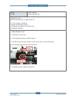
S6-3123

 Error message

Network Problem: IP Con  ict.

 Symptom / Cause 

Network has some problem.
- IP address con  icts with that of other system.
- Communication error 
- There is no response when checking the ping test.

 Troubleshooting method

Change the machine’s IP address.
- Set-up the IP address in this order, Network -> TCP/IP (IPv4) -> STATIC. 

- In case of DHCP or Bootp, reboot the machine to receive a new IP address. 

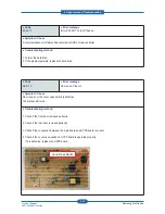
 Code

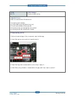
S3-3121

 Error message

Scanner Locked.

 Symptom / Cause 

Scanner lock error has occurred. CIS does not move.

 Troubleshooting method

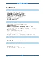
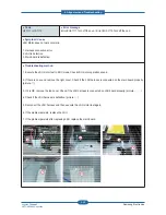
1. Check if the CIS unit is moving when power on.     
2. Check if the   at cable is connected to the CIS unit properly. Re-connect or replace the cable.
3. If the CIS is defective, replace it. 
4. Check if there is any defective part in the scanner unit. (Gear, Belt, Motor etc.)
5. If the problem persists, replace the main board. 

 Code

S4-2111
S4-2112

 Error message

Memory Full. Remove Job.

 Symptom / Cause 

The fax memory is almost full.

 Troubleshooting method

Print or remove the received fax job in Secure Recieve.

Summary of Contents for SCX-483 Series

Page 1: ...SCX 483xFR SCX 5x3x series 600 MHz 3 Printer Languages PCL6 PS3 4 Memory Std Max SCX 483xFD 128 MB 384 MB The keynote of Product SCX 483xFR SCX 5x3x series 256 MB 768 MB 5 Interfaces High Speed USB 2 0 10 100 BaseTX network connector SCX 483xFD 10 100 1000 BaseTX network connector SCX 483xFR SCX 5x3x series 802 11b g n wireless LAN SCX 573xFW 6 Toner cartridge Initial Sales SCX 483x series 2K 2K 5...

Page 2: ...uct Overview 2 1 2 1 2 Features by models 2 2 2 1 3 Speci cations 2 3 2 1 4 Model Comparison Table 2 11 2 2 Product Description 2 12 2 2 1 Front View 2 12 2 2 2 Rear View 2 13 2 2 3 Paper Path 2 14 2 2 4 System layout 2 15 2 2 5 Hardware con guration 2 22 2 2 6 Engine F W Control Algorithm 2 41 2 2 7 S W Descriptions 2 44 3 1 General precautions on disassembly 3 1 3 2 Screws used in the printer 3 ...

Page 3: ...t 3 13 3 3 4 2 Front Rear cover 3 14 3 3 4 3 Paper Path Assy 3 14 3 3 4 4 ADF Pick up unit 3 15 3 3 4 5 ADF Motor 3 15 3 3 5 Middle Cover 3 16 3 3 6 Main board 3 17 3 3 7 HVPS board 3 17 3 3 8 SMPS board 3 18 3 3 9 Laser Scanning Unit LSU 3 18 3 3 10 Fuser unit 3 19 3 3 11 Main drive unit 3 20 3 3 12 Feed drive unit 3 21 3 3 13 Pick up Regi MP clutch 3 21 3 3 14 Pick up roller 3 22 3 3 15 Transfer...

Page 4: ...ooting 4 28 4 2 1 Procedure of Checking the Symptoms 4 28 4 2 2 Error Message and Troubleshooting 4 31 4 2 3 Image Quality problem 4 49 4 2 4 Other errors 4 61 4 2 5 Network problems 4 63 5 1 Block Diagram 5 1 5 2 Connection Diagram 5 3 6 1 Tool for Troubleshooting 6 1 6 2 Acronyms and Abbreviations 6 2 6 3 A4 ISO 19752 Standard Pattern 6 8 6 4 Selecting a location 6 9 chapter 4 Alignment and Trou...

Page 5: ...ement The printer is certi ed in the U S to conform to the requirements of DHHS 21 CFR chapter 1 Subchapter J for Class I 1 laser products and elsewhere is certi ed as a Class I laser product conforming to the requirements of IEC 60825 1 1993 A1 1997 A2 2001 Class I laser products are not considered to be hazardous The laser system and printer are designed so there is never any human access to las...

Page 6: ...ket 6 Use caution when inserting or removing the power connector The power connector must be inserted completely otherwise a poor contact could cause overheating possibly leading to a re When removing the power connector grip it rmly and pull 7 Take care of the power cable Do not allow it to become twisted bent sharply round corners or other wise damaged Do not place objects on top of the power ca...

Page 7: ...ly Please carry out the following procedures before dismantling the printer or replacing any parts 1 Check the contents of the machine memory and make a note of any user settings These will be erased if the mainboard or network card is replaced 2 Ensure that power is disconnected before servicing or replacing any electrical parts 3 Disconnect printer interface cables and power cables 4 Only use ap...

Page 8: ...an get harm 3 When you move the printer This printer weighs approx 16 kg 35 27 lbs including toner cartridge and cassette Use safe lifting and handling techniques Use the lifting handles located on each side of the machine Back injury could be caused if you do not lift carefully 4 Ensure the printer is installed safely The printer weighs approx 16 kg 35 27 lbs ensure the printer is installed on a ...

Page 9: ... conductive foam to prevent electrostatic charge buildup in the vicinity of the assembly 3 Use only a grounded tip soldering iron to solder or desolder ESDs 4 Use only an anti static solder removal device Some solder removal devices not classi ed as anti static can generate electrical charges suf cient to damage ESDs 5 Do not use Freon propelled chemicals When sprayed these can generate electrical...

Page 10: ...cessor SCX 483xFD HD 360 MHz SCX 483xFR SCX 5x3x series 600 MHz 3 Printer Languages PCL6 PS3 4 Memory Std Max SCX 483xFD HD 128 MB 384 MB SCX 483xFR SCX 5x3x series 256MB 768 MB 5 Interfaces High Speed USB 2 0 10 100 BaseTX network connector SCX 483xFD HD 10 100 1000 BaseTX network connector SCX 483xFR SCX 5x3x series 802 11b g n wireless LAN SCX 573xFW 6 ADF SCX 483xFD HD RADF SCX 483xFR SCX 5x3x...

Page 11: ...CX 5739FW Print Copy Scan Fax Hi Speed USB 2 0 IEEE 1284 Parallel Network Interface Ethernet 10 100 Base TX wired LAN Network Interface Ethernet 10 100 1000 Base TX wired LAN Network Interface 802 11b g n wireless LAN Eco printing Duplex 2 sided printing Samsung Easy Printer Manager Memory Tray 2 520 sheets SyncThru Web Service Automatic Document Feeder ADF Reversed Automatic Document Feeder RADF ...

Page 12: ... x 1 200 dpi effective output 2 1 3 2 Copier specification Item SCX 483x series SCX 5x3x series Copy Speed SDMC SDMC Single Document Multiple Copy Simplex to Simplex 1 1 30 sec Simplex to Duplex 1 2 15 sec Duplex to Simplex 2 1 30 sec only 483xFR Duplex to Duplex 2 2 15 sec only 483xFR Simplex to Simplex 1 1 30 sec Simplex to Duplex 1 2 15 sec Duplex to Simplex 2 1 30 sec Duplex to Duplex 2 2 15 s...

Page 13: ...0 ipm 300 dpi 483xFD 24 ipm 300 dpi 483xFR 24 ipm 300 dpi Color 6 ipm 300 dpi 483xFD 8 ipm 300 dpi 483xFR 8 ipm 300 dpi Resolution Optical 1 200 x 1 200 dpi 1 200 x 1 200 dpi Scanning Size ADF DADF Max Document Width 216 mm Effective Scan Width 208 mm Max Document Length 356 mm Effective Scan Lenght 348 mm Max Document Width 216 mm Effective Scan Width 208 mm Max Document Length 356 mm Effective S...

Page 14: ... 203 dpi Fine 196 x 203 dpi 196 x 203 dpi Gray Scale Halftones 256 levels 256 levels Fax Memory Type USB Memory stick USB Memory stick Std 6 MB 50 MB Page Capacity 480 pages 4000 pages 2 1 3 5 Controller S W Item SCX 483x series SCX 5x3x series Processor SCX 483xFD HD 360 MHz SCX 483xFR 600 MHz 600 MHz Memory Std SCX 483xFD HD 128 MB SCX 483xFR 256 MB 256 MB Max SCX 483xFD HD 384 MB SCX 483xFR 768...

Page 15: ...s Citrix Presentation Server Windows Terminal Services WHQL Windows 2000 XP 32 64bits Vista 32 64bits 2003 Server 32 64bits 2008 Server 32 64bits 7 32 64bit 2008 Server R2 64bits Windows 2000 XP 32 64bits Vista 32 64bits 2003 Server 32 64bits 2008 Server 32 64bits 7 32 64bit 2008 Server R2 64bits Compatibility SPL PCL6 Win 2000 XP 32 64bits 2003 Server 32 64bits Vista 32 64bits 2008 Server 32 64bi...

Page 16: ...se TX Internal 483xFR Ethernet 10 100 1000 Base TX Internal Ethernet 10 100 1000 Base TX Internal Wireless Network N A Only SCX 573xFW 802 11n User Interface LCD 483xFD HD 2 Line 483xFR 4 Line 563x series 4 Line 573x series 4 3 inch Touch Screen 2 1 3 6 Paper Handling Item SCX 483x series SCX 5x3x series Standard Capacity 250 sheet Cassette Tray 50 sheet Multi Purpose Tray 80g 250 sheet Cassette T...

Page 17: ...Empty Optional Cassette Tray Capacity 520 sheets 80g 520 sheets 80g Media sizes A4 A5 A6 Letter Legal Folio Oficio Executive ISO B5 JIS B5 A4 A5 A6 Letter Legal Folio Oficio Executive ISO B5 JIS B5 Media types Plain Paper Thin Thick Recycled Bond Cardstock Archive Plain Paper Thin Thick Recycled Bond Cardstock Archive Media weight 16 43lb 60 to 163g 16 43lb 60 to 163g Sensing Paper Empty Paper Emp...

Page 18: ...verage cartridge Yield 5K standard pages Extra High Yield Average cartridge Yield 10K standard pages Declared cartridge yield in accordance with ISO IEC 19752 Key Electronic key CRUM Only Electronic key CRUM Only Life detect Toner gauge sensor by dot count Toner gauge sensor by dot count Drum Yield N A N A 2 1 3 8 Reliability Service Item SCX 483x series SCX 5x3x series Recommanded AMPV 1000 sheet...

Page 19: ...32C 10C to 32C Humidity 20 to 80 20 to 80 Acoustic Noise Level Sound Power Pressure Printing 51dBA 52dBA Standby 26 dBA 26 dBA Sleep Back Ground Level Back Ground Level Power Consumption Ready Less than 50W 563xFR HR Less than 50W 573xFW Less than 65W AVG Less than 600W Less than 650W Power Save Less than 8W 563xFR HR Less than 8W 573xFW Less than 10W Dimension W x D x H SET 483xFD 407 x 424 x 382...

Page 20: ...pm A4 Processor 600 MHz 360 MHz 266 MHz Memory Std Max 256 768 MB 128 384 MB 64 576 MB 64 64 MB Emulation PCL6 PS3 PCL6 PS3 PCL6 PCL6 PS3 MP Cassette 50 250 50 250 50 250 1 250 SCF 520 sheets 520 sheets 250 sheets 250 550 sheets Duplex Std Std Std Std Toner Yield 2K 5K 10K 2K 5K 3K 8K 3 5K 9K Interface High speed USB 2 0 Ethernet 10 100 1000 Base TX High speed USB 2 0 Ethernet 10 100 Base TX High ...

Page 21: ...3 Document feeder input tray 13 Control panel 4 Document feeder output tray 14 Multi purpose tray paper extension 5 Front cover 15 Paper width guides on a multi purpose tray 6 Control board cover 16 Output support 7 Handle 17 Scanner lid 8 Paper level indicator 18 Scanner glass 9 Tray2 optional 19 USB port 10 Tray1 20 Handset X Y Z _ XW XX XY XZ X X X X X_ X NOTE This illustration may differ from ...

Page 22: ...k port 8 Rear cover 3 USB port 9 Tray back cover 4 IEEE 1284 parallel connector optional 10 Telephone line socket 5 Power switch 11 Extension telephone socket EXT 6 Power receptacle X Y Z XX _ XW NOTE This illustration may differ from your machine depending on its model Some features and optional goods may not be available depending on model or country ...

Page 23: ...2 Product specifications and descriptions Service Manual SCX 483x 5x3x series 2 14 Samsung Electronics 2 2 3 Paper Path 1 Simplex 2 Duplex 3 MP ...

Page 24: ... is consisted of the mechanical parts comprising Frame Feeding Developing Driving Transferring Fusing Cassette and H W comprising the main control board power board operation panel PC Interface 1 2 3 4 7 6 8 5 11 10 9 12 14 132 1 LSU 8 Duplex 2 Cartridge 9 Fuser 3 Regi roller 10 Exit roller1 4 MP 11 Exit roller2 5 Feed roller 12 Scanner Platen 6 Pick up roller 13 DADF ADF 7 Cassette 14 OPE ...

Page 25: ...ork of the feed roller The following is a diagram of the pickup section 2 2 4 1 Feeding Part It is consists of a basic cassette an MP tray for supplying different types of media envelope label special paper and parts related to paper transferring 1 Tray The basic tray is located on front side of the machine and allows feeding of common paper Paper size is set using the Size Guides in each tray Adj...

Page 26: ... to feed 50 sheets of general papers 5 Duplex unit It has paper transferring function paper guide function jam removing function It is designed for basic attachment and the duplex feeding takes a side feeding method Usable papers are A4 letter and legal size paper For removing a jam occurred in a front part it is designed to open a cassette and a guide It is designed to open a rear cover to remove...

Page 27: ...ely charged toners are attracted to the latent image due to and electric filed The toners real image on the OPC drum are moved to the transfer media by the positive bias applied to the transfer roller 1 Charging the OPC drum The scorotron gives the drum negative charges 2 Laser exposure Light produced by a laser diode irradiates the charged OPC through the lens and mirrors 3 Development This machi...

Page 28: ...n magnetic 1 element contacting method Toner Non magnetic 1 element shatter type toner The life span of toner ISO 19752 pattern A4 standard Initial toner 2K 483x series 5K 5x3x series Sales toner 2K 5K 10K only 5x3x series Toner Residual Sensor Dot count with CRUM CRU Monitor OPC Cleaning Collect the toner by using cleaning blade Handling of wasted toner Collect the wasted toner in the cleaning fr...

Page 29: ...0 5 2 Thermistor It is a temperatrue detecting sensor Temperature Resistance 7 180 3 Heat roller The heat roller transfers the heat from the lamp to apply a heat on the paper The surface of a heat roller is coated with Teflon so toner does not stick to the surface 4 Pressure roller A pressure roller mounted under a heat roller is made of a silicon resin and the surface also is coated with Teflon W...

Page 30: ...e OPC drum is turned with the paper feeding speed The HSYNC signal is created when the laser beam from LSU reaches the end of the polygon mirror and the signal is sent to the controller The controller detects the HSYNC signal to adjust the vertical line of the image on paper In other words after the HSYNC signal is detected the image data is sent to the LSU to adjust the left margin on paper The o...

Page 31: ...S GND 24V GND 1 2 3 4 CN3 SM PS GND 24V OFF Relay 24VS Fuser ON 1 2 3 4 5 CN4 SM PS GND 24V OFF Relay 24VS Fuser ON 5 4 3 2 1 CN18 2mm S MP S Y z GND GND 24VS 1 2 3 CN12 2m m M AI N FA N 24VS 1 GND 2 CN11 2m m SM PS F AN 12 11 10 9 8 7 6 5 4 3 2 1 GND CLK DIO 3 3V_CRUM 1 2 3 4 CN23 2mm CRUM ltw z ylnp z 3 3V S GND P _E mpt y S ENS 3 3V S GND REG I_S ENS 3 3V S GND FE ED_S ENS 1 2 3 4 5 6 7 8 9 CN ...

Page 32: ... board DDR2 memory and external memory to perform printing and Scan jobs successfully The OPE Controller displays the status of the system using 16 x 2line LCD in response to user actions or the Main controller The HVPS supplies high voltage for developing Process High Voltage controlled by PWM signal from CPU SMPS makes 5V and 24V DC from 220V or 110 AC ...

Page 33: ...CF _TXD SCF _RXD N C nSCF _OPT N C N C GND GND GND GND GND 1 2 3 4 5 6 7 8 9 10 11 12 13 14 15 16 17 18 OPE_LCD LCD 4 Line CLX 5737FW VB US DM DP GND 1 2 3 4 CN USB_IF V BUS DM DP GND US V B DM DP GND 1 2 3 4 5 6 7 8 CN USB_IF US V B DM DP GND GND 1 2 3 4 5 CN USB_IF V BUS DM DP WA KE UP GND 1 2 3 4 5 CN USB_IF Flash Drive Direct USB OPE I F WLAN FDI CLX 5737FW B _V I N GND G _V I N GND R_V I N GN...

Page 34: ...ing jobs successfully The OPE Controller displays the status of the system using 16 x 4line LCD SCX 483xFR 563xFR model or 4 3 TFT LCD SCX 573xFW model in response to user actions or the Main controller The HVPS supplies high voltage for developing Process High Voltage controlled by PWM signal from CPU SMPS makes 5V and 24V DC from 220V or 110 AC WLAN module is used for wireless communication SCX ...

Page 35: ... and descriptions Service Manual SCX 483x 5x3x series 2 26 Samsung Electronics Circuit Board Locations The following diagrams show the locations of the printer circuit boards HVPS SMPS Main Controller FAX WLAN Only SCX 573xFW ...

Page 36: ...nd N W PHY Network USB Device Main Controller Diagram Power S W CPU Chorus 3 Clock 360Mhz OPE 2line Buzzer Power S W HVPS Board MHV THV DEV_DC FUSER _BIAS LSU 2BEAM SCF Rst Rx Tx REQ 540 UART x 4 USB 2 0 MAC I2C x 2 DDR2 128 M ONBOARD 256MB 1 DIMM NCRUM PHY IC AC201A1KMLG 10 100 LAN USB Device ADF Unit Modem Conexant ISP1582 EEPROM 64K LSU controller DDR2 controller SCAN IF AFE GPIO PWMx 12 DAC AD...

Page 37: ...bin Full Sensor Rear Cover 16 Parallel Option DC supply jack 4 CRUM 17 Exit Sensor 5 THERMISTOR 18 Air temp 6 FAN Middle 19 FAN SMPS 7 FAN Main 20 Main Motor Clutch 8 HVPS 21 SCF 9 Paper Empty Regi Feed sensor 22 DDR2 Dimm 10 OPE 23 SMPS Signal 11 CIS 24 SMPS Power 12 ADF 25 MP 13 Scan Motor 26 LSU Information SEC CODE JC92 02351A PBA Name PBA MAIN 2 1 3 4 5 6 7 8 9 10 11 13 12 14 15 16 17 18 19 2...

Page 38: ...Y Network USB Device Wireless Module Main Controller Diagram Power S W CPU Chorus Clock WWMhz vwlMsjkGky i GSGw GzV o wzGi Oto S o Skl kj Sm zly iphzP sz Yilht zjmG Wf Oy Sy S SylxP hy G G ziGYUWG thj pYjG GY kkyYGY tG vuivhykG R XYtiGkpttG ujy t PHY IC RTL8211D n shu zi k hkmG z t Sz O P Sj OZP t G j sz G kkyYG zjhu pmGVGhml nwpv w tG G y j y jG m OZYtP Gvz l Tz Gf Ol SGm SGl SG y Sv G G SGtwSG h...

Page 39: ...NSOR Rear Cover 5 Fuser 6 CRUM 7 FAN Middle 8 HVPS 9 USB OPE 10 WLAN 11 OPE 12 CIS 13 DADF 14 FAN Main 15 LSU 16 Scan Motor 17 EDI 18 MP 19 Ethernet 20 SMPS Power 21 USB Device 22 Parallel Option DC supply jack 23 SMPS Signal 24 DDR2 SODIMM 25 Debug 26 Exit Sensor 27 FAN SMPS 28 SCF 29 Main Motor 30 Air temperature Information SEC CODE JC92 02350B PBA Name PBA MAIN 2 1 3 4 5 6 7 8 9 10 11 12 13 14...

Page 40: ...DICATOR LED INDICATOR STATUS MODE ANIMATION POWER ECO KEY INPUT KEY INPUT WPS OPE MICOM STM8Sp103K3MAFTR S3C828B S3C2415XH 40 OPE MICOM STM8Sp103K3MAFTR S3C828B S3C2415XH 40 C P U CHORUS3 CHORUS4 C P U CHORUS3 CHORUS4 OPE_TX OPE_RX OPE_RST LCD DISPLAY VHX1620BHRC9 2Line VHF12642 4Line LMS430HF14 4 3inch TFT LCD DISPLAY VHX1620BHRC9 2Line VHF12642 4Line LMS430HF14 4 3inch TFT LED INDICATOR LED INDI...

Page 41: ... SCX 573xFW model The Wireless LAN Module supports 802 11b g n at only SCX 5737FW model via USB 2 0 high speed The Module is installed at the USB Host Channel of Main Controller PBA Information SEC CODE JC92 02324B PBA Name PBA OPE MAIN GUI for SCX 573xFW Information SEC CODE JC07 00017A PBA Name LCD 4 3 inch TFT Information SEC CODE JC92 02365A PBA Name PBA OPE KEY SUB ...

Page 42: ...DIMM PBA Optional The SO DIMM PBA is the system Memory module of the Main Controller It is used for the operating system some system application programs and it stores some print data from the USB and Network port There are two kinds of SO DIMM PBA 256MB capacity SCX 483xFD 512MB capacity SCX 483xFR 563xFR 573xFW Information SEC CODE JC92 02087B 512MB PBA Name PBA MAIN DIMM ...

Page 43: ...rol board It use UART communication with main controller S3F443FX is used as a microcontroller Information SEC CODE JC92 02387A PBA Name PBA ADF 2 2 5 5 SCF PBA Optional The ADF SUB PBA SCX 483xFD is the Joint Board to Connect between ADF Module and Main board The JOINT PBA SCX 483xFR 563xFR 573xFW is the Joint Board to Connect between DADF Module and Main board Information SEC CODE JC92 02353A PB...

Page 44: ...n Controller 2 2 5 8 Connection Part Controller require connections to all of the system units such as the BLDC motor Clutch Sensor and other PBAs OPE HVPS SMPS The Main Controller contains various types of connectors to deliver electronic signals through signal wires The signal wires provide electronic control signals that are used for starting and stopping the motors operating clutches sensing t...

Page 45: ...at Lamp Capacity 850W Information 110V 220V SEC CODE JC44 00095D JC44 00096D PBA NAME SMPS V1 SMPS V2 Connection 1 INPUT_AC 2 Fuser_AC Output 3 SMPS Control Signal from Engine PBA 4 OUTPUT_5V 24V to DC POWER PBA 1 2 3 4 1 2 3 4 2 2 5 9 SMPS Board The SMPS Switching Mode Power Supply Board supplies electric power to the Main Board and other boards through a Main Controller The voltage provided incl...

Page 46: ...n General Input Output Voltage 1 AC 110V 90V 135V 2 AC 220V 180V 270V 3 Output Current 5V 2 4A 24V 3 0A 4 Output Power 5V 12W 24V 72W 5 Heat Lamp Capacity 850W Information 110V 220V SEC CODE JC44 00097E JC44 00090E PBA NAME SMPS V1 SMPS V2 Connection 1 INPUT_AC 2 Fuser_AC Output 3 SMPS Control Signal from Engine PBA 4 OUTPUT_5V 24V to DC POWER PBA ...

Page 47: ...V 1240V 6 OPC 51V 3 DEV 338V 7 THV 1315V 1000V 4 BLADE 389V 8 FUSER BIAS 240V Information SEC CODE JC44 00197A PBA Name HVPS 1 2 3 4 5 6 7 8 1 2 3 4 5 6 7 8 2 2 5 10 HVPS Board The SCX 483x 5x3x series contains a High Voltage Power Supply HVPS board This board generates high voltage channels which includes MHV DEV BLADE SUPPLY OPC THV and FUSER BIAS ...

Page 48: ... used to transfer and receive FAX data through a telephone line This PBA is controlled by the Main PBA and has two connectors one for the telephone line connection and the other for an external phone connection 1 2 3 4 5 Connection 1 Main Interface 2 Speaker 3 Hook only China 4 Tel Line 5 Ext Line Information SEC CODE JC92 01746A JC92 01746C only China PBA Name SFX336 MODEM FAX MODULE ...

Page 49: ...utch CLUTCH ELECTRIC JC47 00033A S1 Cassette paper empty sensor PHOTO INTERRUPPTER 0604 001393 S2 MP paper empty sensor PHOTO INTERRUPPTER 0604 001393 S3 Regi sensor PHOTO INTERRUPPTER 0604 001393 S4 Feed sensor PHOTO INTERRUPPTER 0604 001393 S5 Exit sensor PHOTO INTERRUPPTER 0604 001393 S6 Outbin full sensor PHOTO INTERRUPPTER 0604 001393 S7 Home position sensor PHOTO INTERRUPPTER 0604 001415 F1 ...

Page 50: ...sensor the trailing edge of the paper cannot pass the feed sensor after predetermined period of time After the leading edge of the paper passes the feed sensor the paper cannot reach the exit sensor after predetermined period of time The paper exists between the feed sensor and the exit sensor JAM 2 After the trailing edge of the paper passes the feed sensor the paper cannot pass the exit sensor p...

Page 51: ...take appropriate action and then the error message is displayed at LCD window or LED informing the error status of the user Low Heat Error When the engine is at stand by printing or warm up mode if the temperature of the fixing unit is lower than the specified temperature at each state and the lower temperature state is maintained during the specified time the engine defines Low Heat Error When th...

Page 52: ...and the error message is displayed at LCD window to inform the error status of the user By Hsync When the polygon motor is ready the LSU sends out the signal called Hsync and used to synchronize with each image line So if the engine does not detect consecutively the signal for a fixed time it defines the Hsync Error If this error happens the engine stops all functions and keeps it at the error sta...

Page 53: ...tand and transfers data to spooler 3 Stand alone Application that offers the various printing application PSU Printer Settings Utility Printer Status Monitor Network Management in Window system 4 Web based Application that offers the same functions as Stand alone Application and RDC Remote Diagnosis Control in Web environment Firmware is made up of 1 Application Emulation that is a interpreter tra...

Page 54: ...eb independent environment on OS 3 Stand alone Application that is a similar Window software as same as above 2 4 Port Monitor that manages the network communication between spooler and Network Interface Card or various additional application and Network Interface Card this is at first make communication logical port manage the data transfer them from spooler to network port and offer the result o...

Page 55: ...e all graphic data of it and send data to host spooler And then the spooler sends the data stream to the printer via USB port Kernel receives this data from Host and then select emulation fit to data and start selected one After emulation job end Kernel sends the output bit map data to Engine using Printer Video Controller by clock type for LSU Engine print the received data to required paper with...

Page 56: ... servicing the machine you must perform as follows 1 Check to verify that documents are not stored in memory 2 Be sure to remove the toner cartridge before you disassemble parts 3 Unplug the power cord 4 Use a clean at surface 5 Replace only with authorized components 6 Do not force plastic material components 7 Make sure all components are in their proper position Releasing Plastic Latches Many o...

Page 57: ...6 001078 SCREW TAPTYPE PH WSP B M3 L10 ZPC WHT SWRCH18A 1 6003 000282 LSU SCREW TAPTYPE BH B M3 L8 ZPC BLK SWRCH18A 5 6003 000196 COVER MIDDLE SCREW TAPTYPE PWH B M3 L10 NI PLT SWRCH18A 4 6003 000264 COVER FRONT SCREW TAPTYPE PWH B M3 L6 ZPC WHT SWRCH18A 2 6003 000264 MP GUIDE TRAY SCREW TAPTYPE PWH B M3 L6 ZPC WHT SWRCH18A 1 6003 000282 CARTRIDGE TONER SCREW TAPTYPE BH B M3 L8 ZPC BLK SWRCH18A 4 ...

Page 58: ...ectronics Service Manual SCX 483x 5x3x series 3 3 Disassembly procedure 3 3 1 Cover 1 Remove the cassette 2 Remove the front cover by releasing both hooks 3 Remove the duplex unit 4 Open the rear cover and then remove it by releasing both hooks ...

Page 59: ...3 Disassembly and Reassembly Service Manual SCX 483x 5x3x series 3 4 Samsung Electronics 5 Remove the left cover 6 Remove the right cover ...

Page 60: ...mbly 3 5 Samsung Electronics Service Manual SCX 483x 5x3x series 3 3 2 Scanner Assy 1 Remove all covers Refer to 3 3 1 2 Remove 5 screws Right x 1 Rear x 3 Front x 1 3 Unplug 3 connectors 4 Lift up and release the Scanner Assy ...

Page 61: ...msung Electronics 3 3 2 1 OPE board 1 Open the DADF unit 2 Unplug the connector after removing the connector cover 3 Lift up and release the DADF unit 4 Open the Scanner 5 Remove 2 screws 6 Turn up OPE Unit 7 Unplug 2 connectors and remove 7 screws 8 Release the OPE board ...

Page 62: ...s Service Manual SCX 483x 5x3x series 3 3 2 2 CIS Unit 1 Remove the DADF unit and OPE unit Refer to 3 3 2 1 2 Remove 5 screws 3 Release the Platen glass unit 4 Unplug the end of the at cable from the CIS and release the drive belt 5 Remove the CIS Unit ...

Page 63: ... 3 Scan Motor 1 Remove the DADF unit OPE unit and Platen glass unit Refer to 3 3 2 1 2 2 Remove 4 screws 3 Release the scan motor after removing 3 screws 3 3 2 4 Home position sensor 1 Remove the Platen glass unit Refer to 3 3 2 2 2 Release the home position sensor after unplugging the connector ...

Page 64: ... 3 3 DADF Unit SCX 563xFR 563xHR 573xFW 1 Open the DADF unit 2 Unplug the connector after removing the connector cover 3 Lift up and release the DADF unit 3 3 3 1 DADF Pick up unit 1 Remove the DADF COVER OPEN 2 Remove the spring Release the shaft holder And then remove the DADF pick up unit ...

Page 65: ...ce Manual SCX 483x 5x3x series 3 10 Samsung Electronics 3 3 3 2 DADF board 1 Remove 4 screws 2 Release the Original Feed Tray 3 Remove 3 screws 4 Remvoe the DADF rear cover 5 Remove the DADF board after removing 2 screws and all harness ...

Page 66: ...Disassembly and Reassembly 3 11 Samsung Electronics Service Manual SCX 483x 5x3x series 3 3 3 3 DADF Motor 1 Remove 8 screws 2 Release the Original Feed Tray 3 Remvoe the DADF rear cover 4 Remove 2 screws ...

Page 67: ...ice Manual SCX 483x 5x3x series 3 12 Samsung Electronics 5 Remove the DADF front cover 6 Remove 3 screws 7 Remove 2 screws on DADF board 8 Remove 1 screw connecting the ground wire 9 Release the DADF drive unit after removing 3 screws ...

Page 68: ... SCX 483x 5x3x series 3 3 4 ADF Unit SCX 483xFR FD HD 1 Open the ADF unit 2 Unplug the connector after removing the connector cover 3 Lift up and release the ADF unit 3 3 4 1 Tray Input 1 Open the ADF top cover 2 Pull and release the rear hinge of the Original Feed Tray ...

Page 69: ...Service Manual SCX 483x 5x3x series 3 14 Samsung Electronics 3 3 4 3 Paper Path Assy 1 Remove the paper path Assy after removing 4 screws 3 3 4 2 Front Rear cover 1 Remove 2 screws 2 Remove the front and rear cover from both sides ...

Page 70: ...e Manual SCX 483x 5x3x series 3 3 4 4 ADF pick up unit 1 Remove 3 E rings 2 Pull the shaft to the direction of arrow 3 Take off the ADF pick up unit 3 3 4 5 ADF motor 1 Remove the paper path Assy after removing 4 screws 2 Remove the motor after removing 2 screws ...

Page 71: ...6 Samsung Electronics 3 3 5 Middle Cover 1 Remove the Scanner Assy Refer to 3 3 2 2 To remove the middle cover remove 2 screws 6 connectors 1 USB cable from the main board 3 Remove 4 screws 4 Release 2 hooks from the rear Hook Hook 5 Lift up and release the middle cover ...

Page 72: ...3 6 Main board 3 3 7 HVPS board 1 Remove the right cover Refer to 3 3 1 Cover 2 Unplug all connectors on the main board 3 Remove 4 screws 4 Release the main board 1 Remove the right cover Refer to 3 3 1 Cover 2 Remove 5 screws 3 Unplug all connectors on the HVPS board 4 Release the HVPS board ...

Page 73: ... SMPS board 3 3 9 Laser Scanning Unit LSU 1 Remove the right cover Refer to 3 3 1 Cover 2 Unplug all connectors on the SMPS board 3 Remove 4 screws 4 Release the SMPS board 1 Remove the Middle cover Refer to 3 3 5 Middle Cover 2 Unplug 2 at cables from the LSU 3 Remove 3 screws 4 Release the LSU ...

Page 74: ...et injured Before replacing it make sure that fuser unit has cooled 1 Open the Frame Rear by pushing both green points 2 Remove the Frame Rear by releasing both hooks 3 Remove the exit sensor holder after removing 2 screws 4 Remove 4 screws CAUTION When reassembling the fuser unit do not forget to tighten these screws 5 Release the fuser unit Frame Rear Frame Rear Exit sensor holder Exit sensor ho...

Page 75: ...ve the left cover Refer to 3 3 1 Cover 2 Remove the Bar coupler 3 Remove the main drive unit after removing 6 screws NOTE When reassembling the main drive unit tighten 6 screws in order as shown above 4 Unplug the connector from the main motor 5 Release the main drive unit Bar coupler Bar coupler 1 2 3 4 5 6 1 2 3 4 5 6 ...

Page 76: ... 3 3 12 Feed drive unit 3 3 13 Pick up Regi MP clutch 1 Remove the main drive unit Refer to 3 3 11 2 Release the feed drive unit after removing 2 screws 1 Remove the feed drive unit 2 For the clutch to require replacement unplug the connector then replace it Regi Pick up MP Regi Pick up MP ...

Page 77: ...te and duplex unit 2 Pull the small tap down then release the pick up roller 1 2 1 2 3 3 15 Transfer roller 1 Remove the top cover Refer to 3 3 5 Middle Cover 2 Release the LSU bracket after removing 4 screws 3 Push the transfer roller holder to the center and release it 4 Remove the transfer roller Transfer roller Transfer roller ...

Page 78: ... unit 1 Remove the front middle right cover 2 Remove 4 screws 3 Separate the MP lower from the MP upper MP retard roller MP pick up forward roller MP retard roller MP pick up forward roller 3 3 17 Bin full sensor 1 Remove the top left cover 2 Release the bin full sensor after unplugging the connector ...

Page 79: ...r 1 Remove the cassette and duplex unit 2 Remove the PLATE FRAME BOTTOM after removing 4 screws 3 Remove the sensor cover after removing 2 screws 4 For the sensor to require replacement unplug the connector then replace it 5 Remove the sensor cover after removing 2 screws Feed sensor Regi sensor Feed sensor Regi sensor ...

Page 80: ...g Electronics Service Manual SCX 483x 5x3x series 3 3 19 Cassette roller Retard roller 6 Unplug the connector then release the empty sensor 1 Remove the cassette 2 Open the COVER CASSETTE 3 Release the Retard roller Empty sensor Empty sensor ...

Page 81: ...ngs and dark images 2 ID Copy Allows you to coy both sides the ID card like a driver s license to a single side of paper 3 Display screen Shows the current status and prompts during an operation 4 Copy Activates Copy mode 5 Fax Activates Fax mode 6 Left Right Arrows Scrolls through the options available in the selected menu and increases or decreases values 7 Menu Enters Menu mode and scrolls thro...

Page 82: ... power off You can also turn the power on or wake up the machine from power save mode by pressing this button 14 Status LED Shows the status of your machine 15 Start Starts a job 16 On Hook Dial When you press this button you can hear a dial tone Then enter a fax number It is similar to making a call using speaker phone 17 Back Sends you back to the upper menu level 18 Scan Activates Scan mode 19 ...

Page 83: ...ters 9 Address Book Allows you to store frequently used fax numbers and email addresses or search for stored fax numbers or email addresses 10 Redial Pause Redials the last number in ready mode or inserts a pause into a fax number in Edit mode 11 Stop Clear Stops an operations at any time 12 Power Turn the power on or off or wake up the machine from the power save mode Press this button until Powe...

Page 84: ...u Enters Menu mode and scrolls through the available menus 18 Scan Activates Scan mode 19 Eco Turn into eco mode to reduce toner consumption and paper usage 20 Direct USB Allows you to directly print les stored on a USB memory device when it is inserted into the USB port on the front of your machine ...

Page 85: ... or off or wake up the machine from the power save mode Press this button until Power Down appears on the display and choose Yes to turn the power off You can also turn the power on or wake up the machine from power save mode by pressing this button 6 WirelessLED Shows the current status of the wireless network connection 7 Status Shows the status of your machine 8 Start Starts a job 9 Log out All...

Page 86: ...t support the display screen on the control panel this feature is not applicable Small amount of toner is left in the cartridge The estimated cartridge life of toner is close Prepare a new cartridge for replacement You may temporarily increase the printing quality by redistributing the toner On A toner cartridge has almost reached its estimated cartridge lifea The cover is opened Close the cover T...

Page 87: ...ring original document jams To avoid tearing the document remove the jammed document slowly and carefully Original paper jam in front of scanner 1 Remove any remaining pages from the document feeder 2 Open the document feeder cover 3 Gently remove the jammed paper from the document feeder 4 Close the document feeder cover ...

Page 88: ...move any remaining pages from the document feeder 2 Open the document feeder cover 3 Gently remove the jammed paper from the document feeder If you see no paper in this area go to next step 4 Open the document feeder 5 Grasp the misfeed paper and remove the paper from the feed area by carefully pulling it 6 Close the document feeder ...

Page 89: ... 1 Remove any remaining pages from the document feeder 2 Gently remove the jammed paper from the document feeder Original paper jam in scanner duplex path NOTE For SCX 4833FR SCX 4835FR SCX 563x Series and SCX 573x Series 1 Remove any remaining pages from the document feeder 2 Open the document feeder cover 3 Open the duplex jam cover ...

Page 90: ...jammed paper gently out of the document feeder Close the duplex jam cover and the document feeder cover If you do not see paper in this area go to the next step 5 Open the document feeder 6 Grasp the misfeed paper and remove the paper from the feed area by carefully pulling it 7 Close the document feeder ...

Page 91: ...step 2 Pull out tray1 3 Remove the jammed paper by gently pulling it straight out If the paper does not move when you pull or if you do not see the paper in this area check the fuser area around the toner cartridge 4 Insert tray 1 back into the machine until it snaps into place Printing automatically resumes In optional tray2 1 Pull out optional tray 2 2 Remove the jammed paper from the machine If...

Page 92: ...ically resumes In the multi purpose tray 1 If the paper is not feeding properly pull the paper out of the machine 2 Open and close the front cover to resume printing Inside the machine 1 Open the front cover and pull the toner cartridge out 3 2 Remove the jammed paper by gently pulling it straight out 3 Replace the toner cartridge and close the front cover Printing automatically resumes ...

Page 93: ...you do not see the jammed paper or if there is any resistance when you pull stop and go to the next step 3 Open the rear cover 4 Remove the jammed paper as shown in the following gure 5 Close the rear cover Printing automatically resumes In the duplex unit area 1 Pull the duplex unit out of the machine 2 Remove the jammed paper from the duplex unit If the paper does not come out with the duplex un...

Page 94: ... 4 14 Samsung Electronics 3 Insert the duplex unit into the machine 4 Open the rear cover 5 Remove the jammed paper as shown in the following gure 6 Return the fuser door and the lever to their original position 7 Close the rear cover Printing automatically resumes 3 3 ...

Page 95: ...orts for maintenance purposes These reports can be used to aid the diagnosis of print quality problems Configuration report Menu System Setup Report Configuration You can print a report on the machine s overall con guration It shows various SW version and current machine setting status Supplies Information report Menu System Setup Report Supplies Info You can print supplies information page It sho...

Page 96: ...vided Printer Software CD 2 Double click the Smart Panel icon on the Noti cation Area in Linux You can also click Smart Panel on the status bar in Mac OS X For Windows user select Start Programs or All Programs Samsung Printers Samsung Easy Printer Manager 3 Click Printer Setting If your machine is connected to the network you can set the altitude via SyncThru Web Service 4 Click Setting Altitude ...

Page 97: ...dition of the appropriate roller No Roller Description Band Period mm Phenomenon Defective part 1 1st Pressure roller 62 8 mm Background Fuser unit 2 2nd Pressure roller 37 7 mm Background 3 Heat roller 77 8 mm Black spot and fuser ghost 4 Charge roller 26 7 mm Black spot Toner cartridge 5 Developer roller 36 78 mm Horizontal band 6 OPC drum 75 49 mm White and Black spots 7 Supply roller 69 57 mm ...

Page 98: ... 1 Using the Samsung Easy Printer Manager program Windows only Samsung Easy Printer Manager is a Windows based application that combines Samsung device settings into one location Samsung Easy Printer Manager combines device settings as well as printing environments settings actions launching applications and so on All of these features provide a gateway to conveniently use Samsung machine Samsung ...

Page 99: ...ary based on the machine selected Some machines do not have this feature 6 Order Supplies Click on the Order button from the supply ordering window You can order replacement toner cartridge s from online Click the Help button from the upper right corner of the window and click on any option you want to know about 4 1 6 2 Using the Smart Panel program Macintosh and Linux only Smart Panel is a progr...

Page 100: ... Update the rmware by using the network 4 1 7 1 Update the firmware by using the USB port Upgrading preparations usblist2 exe Tool which sends rmware data to printer Firmware le to upgrade Upgrade Procedure 1 Turn the machine off 2 Connect USB cable to printer 3 Turn the machine on Check if the printer is the ready status 4 Drag the rmware le and Drop down on the usblist2 exe And then rmware updat...

Page 101: ...te the firmware by using the network Upgrading preparations Wired or Wireless Network connection is established Firmware le to upgrade Upgrade Procedure 1 Open Web browser and input IP address of machine Click Login 2 Log in Admin Mode ID admin PW sec00000 3 Select Maintenance menu and click upgrade wizard ...

Page 102: ... series 4 22 Samsung Electronics 4 Select rmware le using browser button and press next button 5 SyncThru will check verify rmware le and compare version and press next button 6 Machine starts upgrading SyncThru will return home page after upgrading is completed ...

Page 103: ...e and perform various test to isolate the cause of a malfunction While in Tech mode the machine still performs all normal operations To enter the Tech Mode SCX 5737FW GUI model To enter the service mode press 1 2 3 number keys simultaneously When the password dialog box appears enter 1934 and press the OK button SCX 483x 563x series LCD model To enter the Tech Mode press Menu 1 9 3 4 in sequence ...

Page 104: ...one Pulse Tone Modem Speed 33 6 28 8 14 4 12 0 9 6 4 8 33 6 Error Rate 5 10 10 Clear All Mem Toner Low Level 1 30 10 Clear Counts Enter Passcode Total Page CNT FLT Scan CNT ADF Scan CNT Engine Footer On Off HDD Format Dial Tone On Off Machine Test Switch Test REDUCE_PANEL COMPLETE_PANEL Test Param Set Modem Test Dram Test Rom Test Pattern Test Shading Test Shading Print Print EDC Mode Restart Mach...

Page 105: ...ion It is best set 33 6Kbps as default setting Error Rate When the error rate is about exceed the set value the Baud rate automatically adjusts to 2400 bps This ensures that the error rate remains below the set value You can select the rate between 5 and 10 Clear All Memory The function resets the system to factory default settings This function is used to reset the system to the initial value whe...

Page 106: ...chine s DRAM The result appears in the LCD display If all memory is working normally the LCD shows O K ROM TEST Use this feature to test the machine S ROM The result and the software version appear in the LCD display FLASH VER 1 00 V ENGINE VER 1 00V Pattern Test Using this pattern printout you can check if the printer mechanism is functioning properly It is needed in the production progress Servi...

Page 107: ...0 Bond Temp Media type offset for fuser roll temperature 5 0 10 109 0080 0080 Trans Temp Media type offset for fuser roll temperature 5 0 10 109 0090 0090 CardStock Temp Media type offset for fuser roll temperature 5 0 10 109 0100 0100 Envelopes Temp Media type offset for fuser roll temperature 5 0 10 109 0110 0110 Labels Temp Media type offset for fuser roll temperature 5 0 10 110 0070 0070 LD Po...

Page 108: ...or High Low Engine 105 0030 Black MHV Bias Black MHV bias voltage on at normal drive level On Off Engine 106 0030 Black Dev Bias Black Dev bias voltage on at normal drive level On Off Engine 107 0030 Black THV Bias Black THV bias voltage on at normal drive level On Off Engine 107 0031 Black THV Bias Black THV bias voltage on at normal drive level On Off Engine 107 0070 Black THV Bias Read Detect w...

Page 109: ...ity toner product date etc Configuration Con guration report shows the status of the user selectable options You may print this list to con rm your changes after changing settings This page provides useful information for service Error Info Error Information Report shows error records Usage page Usage page report shows usage page counts since service date It shows total counts of the simplex print...

Page 110: ...mptoms Before attempting to repair the printer rst obtain a detailed description of the problem from the customer Power On Red LED on Error message is displayed OPE LED Green OK Print test pattern printing Quality is Nomal Refer to Solution of Image Problem See the troubleshooting for error code END No Power Power Module error Main PBA OPE LED ON ...

Page 111: ...ve any paper fragments caught in the paper path Paper Jam occurs repeatedly at a speci c point in the Paper Path Open the fuser cover Jam clear Dismantle the machine and carefully inspect the region where the jam occurs Especially check if paper fragments are caught in the Fuser 4 Print the Information Page Configuration Try printing a test page from a computer If there is an error check cables an...

Page 112: ...hin speci cation If necessary move the printer 3 Ensure that the printer is position away from any air conditioning or other heating or cooling equipment Also ensure that is not positioned in a direct draft from any air conditioning fan or open window If necessary move the printer 4 Ensure the printer is not positioned in direct sunlight If it is unavoidable use a curtain to shade the printer 5 En...

Page 113: ...ed Out Tray2 Cassette 4 37 page H1 1252 Paper is empty in Tray2 4 38 page M1 1010 M1 1110 Paper Jam in Tray1 4 38 page M1 1210 Paper Jam in Tray2 4 38 page M1 1610 Paper Jam in MP tray 4 39 page M1 2210 Tray2 Door Open Close it 4 39 page M1 3221 Not installed Tray2 4 39 page M1 5112 Paper is empty in tray 1 4 40 page M1 5212 Paper is empty in tray 2 4 38 page M1 5612 Paper Empty in MP Tray 4 41 pa...

Page 114: ...ng Page U1 2340 U1 2341 Error U1 2340 Turn off then on Error U1 2341 Turn off then on 4 48 page U2 1111 U2 1113 Error U2 1111 Turn off then on Error U2 1113 Turn off then on 4 49 page U3 3113 U3 3114 Document jam Remove jam 4 50 page U3 3213 U3 3313 U3 3314 Document jam Remove jam 4 50 page U3 4110 Door of scanner is open 4 50 page ...

Page 115: ...otor is defective 4 Engine board is defective Troubleshooting method First turn the machine off then on If the error persists refer to the following 1 Check if the motor connector is connected properly Reconnect it 2 OPC coupler has overloaded After removing the toner cartridge rotate the OPC coupler Spec 6 kgf cm If there is any damage the OPC coupler can t rotate well Replace the toner cartridge...

Page 116: ...formation report Menu System Setupr Report Supplies Info Check the life remaining of the toner cartridge If its life is at the end turn the machine off and replace the toner cartridge with new one Z Code C1 1410 C1 1411 Error message Install toner cartridge Symptom Cause The toner cartridge is not installed Troubleshooting method 1 Turn the machine off then on 2 Remove the toner cartridge Thorough...

Page 117: ...er cartridge replace with new one Code H1 1210 Error message Paper jam in Tray2 Symptom Cause A paper jam was detected in the feed area of the tray2 1 Paper was inserted abnormally or was not loaded in the cassette properly 2 Pick Up unit has a problem Troubleshooting method 1 Open the Tray2 and remove the jammed paper 2 If there is any defective part in the pick up unit replace it Code H1 1222 Er...

Page 118: ...ace the Main Board Code M1 1010 M1 1110 M1 1210 Error message Paper Jam in Tray1 Paper Jam in Tray1 Paper Jam in Tray2 Symptom Cause The jammed paper has occurred in the tray1 2 1 Pick Up or Torque Limiter Roller is contaminated or worn out 2 There is some obstacles in the paper path Troubleshooting method 1 Clear the jammed paper refer to 4 1 3 2 If the problem persists check the following 2 Whil...

Page 119: ...ing 2 While pushing the Paper Empty Sensor send the printing data Check if the pick up roller is rotating normally 3 Check if there is any obstacles in the paper path from Pick Up to Feed Sensor The feed roller should be especially checked 4 Print out the Supplies Information Check the MP Tray Roller Life and MP Tray Torque Limiter Life If the life came to the end replace the relative roller or MP...

Page 120: ...in the tray1 2 Actuator Paper Empty is defective 3 Photo Sensor is defective or connection is bad 4 Main Board is defective Troubleshooting method 1 Load the paper in the tray1 2 If the Actuator Paper Empty is defective replace it 3 If the Photo Sensor is defective replace it Check if the connector is connected properly Empty sensor Empty actuator Empty sensor Empty actuator 4 If the problem persi...

Page 121: ... the MP tray 2 Actuator Paper Empty is defective 3 Photo Sensor is defective or connection is bad 4 Main Board is defective Troubleshooting method 1 Load the paper in the MP tray 2 If the Actuator Paper Empty is defective replace it 3 If the Photo Sensor is defective replace it Check if the connector is connected properly Empty sensor Empty actuator Empty sensor Empty actuator 4 If the problem per...

Page 122: ...obstacles in the paper path 4 The driving for the toner cartridge has some problem 5 The driving for the fuser unit has some problem Troubleshooting method 1 Remove the jammed paper If the error persists check the followings 2 Check if the feed sensor connector is connected properly Feed sensor Regi sensor Feed sensor Regi sensor 3 Check if the Regi roller is contaminated or worn out If yes replac...

Page 123: ...or was not assembled properly Troubleshooting method 1 Remove the jammed paper 2 Remove the contamination or obstacles in the paper path 3 Adjust the paper guide properly 4 Check if the exit sensor is assembled properly Reassemble it Code M3 1110 Error message Paper Jam in exit area Symptom Cause A paper jam was detected in the exit area 1 There is some obstacles in the paper path Troubleshooting ...

Page 124: ...ected that the output tray has got full or the bin full sensor is defective 1 Output tray is full 2 Outbin full sensor connection is wrong Troubleshooting method 1 Remove the paper on the output tray The maximum loading capacity is 150 sheets based on standard paper 80g m2 2 Check if the Bin full Sensor connector is connected properly Reconnect it or replace the Bin full sensor ...

Page 125: ...Check if the rear door is closed perfectly 3 Check if the connection between the main board and HVPS board is correct 4 Check if the cover open switch on HVPS board is operated properly If it is defective replace the HVPS board Cover Open Switch Cover Open Switch Code S1 2411 Error message Error S1 2411 Turn off then on Symptom Cause A communication error failure has occurred at HDD of main contro...

Page 126: ...he machine to receive a new IP address Code S3 3121 Error message Scanner Locked Symptom Cause Scanner lock error has occurred CIS does not move Troubleshooting method 1 Check if the CIS unit is moving when power on 2 Check if the at cable is connected to the CIS unit properly Re connect or replace the cable 3 If the CIS is defective replace it 4 Check if there is any defective part in the scanner...

Page 127: ... setting up for 802 1x con rmation server Re enter the server information and con rmation protocol Re enter the user information Code U1 2320 Error message Error U1 2320 Turn off then on Symptom Cause The temperature control of fuser unit is abnormal Open Heat Error Troubleshooting method 1 Turn the machine off Re install the fuser unit Then turn the machine on Is the error message is disappeared ...

Page 128: ...ser connector is connected properly b Check if the input voltage is normal c Check if the thermistor is twisted or contaminated Code U1 2340 U1 2341 Error message Error U1 2340 Turn off then on Error U1 2341 Turn off then on Symptom Cause The temperature control of fuser unit is abnormal Over Heat Error Troubleshooting method 1 Turn the machine off Re install the fuser unit Then turn the machine o...

Page 129: ...thod 1 Execute the LSU motor test in EDC mode Check LSU motor operation sound 2 If there is no sound remove the right cover Check if the LSU harness is connected on the main board properly picture 3 If it is OK remove the top cover Check if the LSU harness is connected on LSU board properly picture 4 Check if the LSU harness is defective picture 5 Reconnect the LSU harness and then execute the LSU...

Page 130: ...e problem persists turn the machine off then on 3 Open the ADF DADF COVER OPEN Check if the roller in pick up unit is worn out or contaminated Replace the pick up unit 4 If the document jam occurs continually check the following a Check if the ADF DADF drive unit is working normally b Check if the connection between ADF DADF and scanner is OK Code U3 4110 Error message Door of scanner is open Symp...

Page 131: ...ing 2 Dark black vertical band occur in the printing 3 Partly depression or deformation on the surface of the transfer roller 2 Scratched surface of the charge roller in the toner cartridge 1 Damaged develop roller in the Toner cartridge Deformed Doctor blade or cleaning blade If causes 1 and 2 occur in the toner cartridge replace the toner cartridge and try to print out Replace the transfer rolle...

Page 132: ...les between the toner cartridge roller and blade In case the life of the toner cartridge has been expired white lines or light image occur in front of the image 1 Foreign matter stuck onto the window of internal lenses of LSU mirror Foreign matter stuck onto the window Clean the LSU window with recommended cleaner IPA Clean the window with a clean cotton swab Replace the toner cartridge No 3 Remov...

Page 133: ... contacts of the voltage terminals to developer Clean each voltage terminal of the Charge Supply Develop and Transfer roller remove the toner particles and paper particles 1 Clean the right Gear that has relatively small gap of the teeth in the OPC 2 If the malfunction persists replace the developer Charge roller 26 7 mm Developer roller 36 78 mm OPC drum 75 49 mm Supply roller 69 57 mm Charge rol...

Page 134: ...cleanly remove foreign substances stuck on the OPC location equivalent to black spots and white spots with a dry duster 1 The transfer roller guarantees 50 000 sheets printing If the roller s life is expired replace it 2 In case of 26 7 mm interval unremovable in 1 take measures as to replace the develop er cartridge and try to print out 5 Clean the inside of the set against the paper particles an...

Page 135: ...high voltage terminal in the HVPS and the one in the set 4 Abnormal output from the HVPS 1 Develop roller is stained when the toner of toner cartridge is almost consumed Check if the Toner Save mode is off Replace the developer cartridge and try to print out Wait 30 minutes after printer is powered on before you start printing 1 Clean up the contaminated area by the toner 2 Replace the HVPS if the...

Page 136: ...RCP Change to Normal and test Works correctly with 450V of Bias voltage Works correctly after replaced LSU Repair or replace the defective component The power of LSU is set high or internal problem Replace LSU or adjust volume Same at Normal END NO NO NO Toner over supply due to the adjustment fault of metering blade in toner cartridge Replace toner cartridge NO YES YES YES YES ...

Page 137: ...d right 2 The toner level is not even on the developer roller due to the bad blade 1 The pressure force on the left and right springs of the transfer roller is not even the springs are damaged the transfer roller is improperly installed or the transfer roller bushing or holder is damaged Replace both the left and right Spring Holder Replace the toner cartridge ...

Page 138: ... the transfer roller smooth 5 Is the HVPS normal 2 Does recycle paper be used 1 Does character exist less than 2 per a page and hasn t it been used long time The toner cartridge is basically designed to print 2 000 sheets with 5 image Replace the toner cartridge when the life span of it has been ended The A S is not guaranteed if using recycle paper If the problem is still not solved replace the t...

Page 139: ...ticles between high voltage terminal in the main body and the one in the HVPS board 1 Bad contacts caused by contamination from toner particles between high voltage terminal in the main body and the electrode of the Developer Clean the terminals when contaminated by toner particles Replace the Main board if not solved by the above directions 1 2 Occur in the toner cartridge replace the developer a...

Page 140: ...he Face of Page Description The background on the face of the printed page is stained 2 If the transfer roller is contaminated stains on the face of page will occur 1 T oner leakage due to improperly sealed developer Replace the toner cartridge If the transfer roller is contaminated print the 2 3 blank pages ...

Page 141: ...iption The back of the page is stained at 47 mm intervals 1 Transfer roller is contaminated Replace the transfer roller 2 Pressure roller is contaminated Disassemble the fuser and clean the H R Heat Roller and P R Pressure roller And check the area between H R and Thermistor If contaminated clean the area not to be deformed ...

Page 142: ...he path between Main board and HVPS Repair or replace the defective component or board The mirror in LSU might be misplaced so the light path to the OPC deviates Repair or replace LSU or remove any defective matters in the machine Self test pattern prints No image Self testing is possible Is the OPC terminal of machine is well connected to Frame Does the video data line to LSU transit to High Low ...

Page 143: ... errors 1 Multi Feeding Description Multiple sheets of paper are fed at once 1 Clutch malfunction the solenoid does not work properly 2 Pick up Retard Forward roller are contaminated with foreign matter Replace the solenoid if necessary Clean the contaminated roller with soft cloth with Isopropyl Alcohol ...

Page 144: ... system power is turned on all lamps on the operator panel do not come on 1 Check if the power input and SMPS output are normal 2 Check if the OPE connector is connected properly OPE harness or OPE board is defective Replace the power supply cord or SMPS 1 Reconnect the OPE harness 2 Replace the OPE harness or OPE board ...

Page 145: ...ity name check When SNMP no response Check Point Action LAN cable check A Connected or Not connected B Wrong cable defected cable crossover cable C Connection connector Link partner check Network LED check A Link LED check Link LED On when connected B Activity LED check No packet Regularly blinking packet random blinking depend on Printer Model Print Network test page A Printed correctly If not NI...

Page 146: ...t check A IP address Con ict Same IP address in a network Unplug network cable and PING test at other PC 2 Protocol Enable Disable Port Number in printer driver Factory Default 1 Network Value changed to default value A Some of Network value will not be changed immediately B Factory default operation will be done after Power Off Power On ...

Page 147: ...OM 64K LSU controller DDR2 controller SCAN IF AFE GPIO PWM x 12 DAC ADC RTC RTC battery Flash 16M for OS Engine TBD Solenoid MP Pickup Regi Sensor Exit Feed Empty Regi Out bin full MP ADF_DET ADF_POS ADF_COVER Duplex Fan Ma in SMPS MIDDLE Motor Cover S W Debug MAINBOARD Fuser thermistor 1 BLDC STEP A3983 Serial Flash 8M for FAX Flash DCDC ST1S10 THV read LD power SPI CIS Scan Unit USB HOST DCDC ST...

Page 148: ...SGm SGl SG y Sv G G SGtwSG hkm kl SGhkm wvzSG hkm jv lySGk P Tm Ot S ztwz SGtpkkslP t j GzV k thpuivhyk m XGiskj m DCDC ST1S10 o G skG zwp jpzGz G z Gt OXP ziGovz OZP T mkp T nG ziGm G T k Gw DCDC ISL88550 A DCDC ST1S10 3 3V system 1 8V DDR2 ztwzO wlZP Y XSY YSG ztwzS mkiSGy z LAFE1001 zj T Z m Rainier SCX 4833FR SCX 5637FR SCX 5737FW Block Diagram V0 3 2010 09 30 h 5V 0 9V VTT z lw hZ _Z oV wyv l...

Page 149: ...3V _CRUM 1 2 3 4 CN23 2mm CRUM ltw z ylnp z 3 3V S GND P _E mpt y S ENS 3 3V S GND REG I_S ENS 3 3V S GND FE ED_S ENS 1 2 3 4 5 6 7 8 9 CN 2mm SENSOR 24VS MP _CLT 3 3V S GND MP _SE NS 1 2 3 4 5 CN 2mm MP mllk z 24V S GND THV_RE A D nTHV_E N P WM_THV P WM_DE V_DC P WM_MHV A S _B I P WM_FUS E R GND GND 3 3V S 3 3V _Cover_Open CN8 1 5mm SCF_IF 3 3V _LS U nHsy nc GND V DO_1_P V DO _1_N GND nS H_1 nS H...

Page 150: ... WA KE UP GND 1 2 3 4 5 CN USB_IF Flash Drive Direct USB OPE I F WLAN FDI CLX 5737FW B _V I N GND G _V I N GND R_V I N GND 3 3V _CI S 3 3V _CI S SCA N_CT R CI S_S P CIS _CLK LE D_COM MO N CI S_B LE D CIS _GLE D CI S_RLE D GND 1 2 3 4 5 6 7 8 9 10 11 12 13 14 15 16 CN FFC 1mm CIS _IF OUT1A OUT1B OUT2A OUT2B 1 2 3 4 CN 2mm SCAN_MTR MT STEP GND GND DA DF _REGI _SOL nS ENS _DADF_P _DET nS ENS _DADF_P ...

Page 151: ...Troubleshooting The following tools are recommended safe and easy troubleshooting as described in this service manual DVM Digital Volt Meter Standard Indicates more than 3 digits Driver Standard type type M3 long M3 short M2 long M2 short Tweezers Standard For general home use small type Cotton Swab Standard For general home use for medical service Cleaning Equipments Standard An IPA Isopropyl Alc...

Page 152: ... for Rapid Fast Fusing EH S Samsung Environment Health Safty ESMTP Extended Simple Mail Transfer Protocol EP Electro Photography EPC Electric Pre Collation FCOT First Copy Out Time FDI Foreign Device Interface FIA Foreign Interface Attachment FRU Field Replaceable Unit FPOT First Print Out Time GW GateWay HH High Temperature High Humidity Testing Chamber conditions HPVC Halftone Printing Video Con...

Page 153: ... Per Minutes PQ Print Quality PS 3 PostScript Level 3 PVC Printing Video Controller in the SPGPm Graphic Processor for Printer QCD Quality Cost and Delivery RCP Remote Control Panel RT OS Real Time Operating System RX Receive S2E Scan To Email SAD Solid Area Density SC Service Call SCF Second Cassette Feeder SDSP Single Document Single Printout SDMP Single Document Multiple Printout SDR Shut Down ...

Page 154: ...ti Purpose Bypass tray PBA MAIN MAIN PBA Printed circuit Board Assembly PMO CONNECT PAPER MFP MFP Multi Functional Peripheral FAN DC DC Direct Current CBF POWER STITCH GRAY CBF Cable Form MEA UNIT GUIDE CST PA ASS Y CST Cassette Paper tray PA Paper PBA LIU PBA Printed circuit Board Assembly LIU Line Interface Unit for FAX SHIELD P_MAIN LOWER P Press CBF HARNESS LIU GND LIU Line Interface Unit for ...

Page 155: ...ctrical connector D Sub a kind of the connector type shape D COVER M CCD CABLE M Mold CCD Charge Coupled Device COVER SCAN LOWER UMAX UMAX Supplier s name for CCD module ICT INSERT SHAFTI ICT Iron Cutting IPR BRK SCAN BD IPR Iron Press BRK Bracket BD Board CBF SIGNAL CCD FFC CCD Charge Coupled Device FFC Flexible Flat Cable COVER M OPE M Mold OPE Operation Panel Control Panel KEY M COPY M Mold PLA...

Page 156: ...ass tray Sensor A S MATERAL PICKUP MP FOOT ML80 HOLDER CATCH CST MC2 MC2 McKInley2 Samsung Project code name IPR GROUND PLATE A OPC OPC Organic Photo Conductive ELA M M AUD SPEAKER ELA M M Electrical Assembly M M AUD Audio CBF HARNESS OPC GND OPC GNG Organic Photo Conductive Ground IPR GROUND PLATE SCF SCF Second Cassette Feeder Tray2 PBA SUB PTL PBA SUB PTL Sub Printed circuit Board Assembly for ...

Page 157: ...RING R CAU HOT FU CAU HOT FU Caution Hot Fuser PMO ARM ACTUATOR PMO ARM Processing Mold Arm LABEL R HV FUSER HV High Voltage 220V LABEL R LV FUSER LV Low Voltage 110V PPR SPONG SHEET PPR Plastic Press IPR P_PINCH SCAN I PR P Iron Press ROLLER REGI REGI Registration PBA SUB REGI PBA SUB REGI Sub Printed circuit Board Assembly for the Registration GROUND P_SCAN ROLLER GROUND P Ground Press IPR GUARD...

Page 158: ...he Test The sample pattern shown in below is the standard pattern used in the factory The life of the toner cartridge and the printing speed are measured using the pattern shown below The image is 70 of the actual A4 size 6 3 1 A4 ISO 19752 Standard Pattern This test page is reproduced at 70 of the normal A4 size ...

Page 159: ...or opening covers and trays The area should be well ventilated and away from direct sunlight or sources of heat cold and humidity Do not set the machine close to the edge of your desk or table Clearance space Front 482 6 mm enough space so that the paper tray can be removed Back 180 mm enough space for ventilation Right 100 mm enough space for ventilation Left 100 mm enough space for ventilation ...

Page 160: ...CL6 PS3 4 Memory Std Max SCX 483xFD 128 MB 384 MB SCX 483xFR SCX 5x3x series 256 MB 768 MB 5 Interfaces High Speed USB 2 0 10 100 BaseTX network connector SCX 483xFD 10 100 1000 BaseTX network connector SCX 483xFR SCX 5x3x series 802 11b g n wireless LAN SCX 573xFW 6 Toner cartridge Initial Sales SCX 483x series 2K 2K 5K SCX 5x3x series 5K 2K 5K 10K SCX 483x series SCX 563x 573x series ...

Page 161: ...USER 12 3 FRAME REAR 14 4 FRAME 16 4 1 MP 21 4 2 DRIVE 23 4 3 DRIVE FEED 25 4 4 DUPLEX 27 5 MFA SCX 573xFW 29 5 1 PLATEN SCX 573xFW 31 6 MFA SCX 483xFR 563xFR 5637HR 33 6 1 PLATEN SCX 483xFR 563xFR 5637HR 35 7 MFA SCX 483xFD HD 37 7 1 PLATEN SCX 483xFD HD 39 8 PLATEN A4 MIDDLE 41 9 DADF SCX 573xFW 563x series 483xFR 43 9 1 DADF LOWER 45 9 2 DADF UPPER 47 9 3 DADF PLATEN 49 10 ADF SCX 483xFD HD 51 ...

Page 162: ...CX 483x 563x 573x series Samsung Electronics Service Manual Thumbnail 0 Main 4 FRAME 5 MFA SCX 573xFW 1 COVER 1 1 COVER MIDDLE 2 FUSER 2 1 FRAME REAR 4 1 MP 4 2 DRIVE 4 3 DRIVE FEED 4 4 DUPLEX 5 1 PLATEN SCX 573xFW 6 MFA SCX 483xFR 563xFR HR 6 1 PLATEN SCX 483xFR 563xFR HR 7 MFA SCX 483xFD HD ...

Page 163: ...ng Electronics Service Manual Parts Catalog SCX 483x 563x 573x Series Samsung Electronics Service Manual Thumbnail 7 1 PLATEN SCX483xFD HD 10 ADF 9 DADF 9 1 DADF LOWER 9 2 DADF UPPER 9 3 DADF PLATEN 11 CASSETTE 12 OPTION CASSETTE 8 PLATEN A4 MIDDLE ...

Page 164: ...6 Parts Catalog SCX 483x 563x 573x Series Samsung Electronics Service Manual Parts Catalog SCX 483x 563x 573x series Samsung Electronics Service Manual 0 Main 2 4 0 6 5 1 9 3 7 10 11 12 8 ...

Page 165: ... 4 FRAME 3 JC97 03904A MFA 1 SNA SCX 573xFW Refer to 5 MFA 3 JC97 03900A MFA 1 SNA SCX 563xFR Refer to 6 MFA 3 JC97 03900H MFA 1 SNA SCX 563xHR Refer to 6 MFA 3 JC97 03906A MFA 1 SNA SCX 483xFR Refer to 6 MFA 3 JC97 03902A MFA 1 SNA SCX 483xFD HD Refer to 7 MFA Drawer Part Code Description Qty Service Remark 4 JC95 01300A COVER REAR DUPLEX 1 SNA Excepting XAA 5 JC90 01036A CASSETTE 1 SA Refer to 1...

Page 166: ...83x 563x 573x Series Samsung Electronics Service Manual Parts Catalog SCX 483x 563x 573x series Samsung Electronics Service Manual 1 1 1 1 2 1 3 1 3 1 4 2 3 3 1 3 2 4 4 1 4 2 5 5 1 5 2 5 2 5 3 5 4 5 5 5 5 5 6 5 7 0 1 COVER ...

Page 167: ... SCX 563xFR 2 JC95 01324B COVER MIDDLE 1 SNA SCX 573xFW 2 JC95 01324C COVER MIDDLE 1 SNA SCX 4833HR SCX 5637HR 3 JC95 01325A COVER RIGHT 1 SNA SCX 4833 series 3 JC95 01325B COVER RIGHT 1 SNA SCX 5x37 series 3 1 JC63 02935A COVER RIGHT 1 SNA SCX 4833 series Drawer Part Code Description Qty Service Remark 3 1 JC63 02935B COVER RIGHT 1 SNA SCX 5x37 series 3 2 JC63 02936A COVER DIMM 1 SNA 4 JC95 01326...

Page 168: ...10 Parts Catalog SCX 483x 563x 573x Series Samsung Electronics Service Manual Parts Catalog SCX 483x 563x 573x series Samsung Electronics Service Manual 1 3 2 7 5 8 9 6 4 7 7 10 12 11 0 1 1 COVER MIDDLE ...

Page 169: ...VER EXIT 1 SA 3 JC63 01927A COVER L_FAX_BOARD 1 SA 4 JC61 04098A STACKER BIN_FULL 1 SA 5 JC63 02939A GROUND FAX 1 SNA 6 JC72 01343A PMO SUB_M_STACKER 1 SA 7 6003 000196 SCREW TAPTYPE 3 SNA 7 6003 000196 SCREW TAPTYPE 4 SNA SCX 573xFW Drawer Part Code Description Qty Service Remark 8 JC67 00055A BRUSH ANTISTATIC 531P 1 SA 9 3001 002262 SPEAKER 1 SA 10 JC31 00146A FAN 1 SA 11 JC92 02364A PBA WNPC 1 ...

Page 170: ...ts Catalog SCX 483x 563x 573x series Samsung Electronics Service Manual 2 FUSER 0 40 25 37 30 30 42 42 42 37 37 37 10 20 28 10 10 10 13 13 13 13 23 38 31 23 8 21 36 6 19 19 19 19 5 7 7 3 27 34 1 22 32 14 15 4 33 12 11 12 18 24 24 11 18 5 15 29 17 5 30 2 16 6 13 7 39 26 21 8 6 5 9 35 ...

Page 171: ...15 6601 001725 BEARING BALL 2 SNA 16 JC39 01487A HARNESS FUSER JOINT 1 SA 17 JC39 01488A HARNESS FUSER CON 1 SA 18 JC61 01960A BUSH PR_1ST 2 SNA 19 JC61 02154A GUIDE CLAW 4 SNA 20 JC61 02631A GUIDE GROUND_PR 1 SNA Drawer Part Code Description Qty Service Remark 21 JC61 04085A HOLDER JAM 2 SNA 22 JC61 04092A FRAME FUSER 1 SNA 23 JC61 04093A BUSH HR 2 SNA 24 JC61 04095A BUSH PR_2ND 2 SNA 25 JC61 040...

Page 172: ...rts Catalog SCX 483x 563x 573x Series Samsung Electronics Service Manual Parts Catalog SCX 483x 563x 573x series Samsung Electronics Service Manual 3 FRAME REAR 3 5 0 9 3 11 7 8 11 3 11 11 2 10 10 6 6 6 6 4 ...

Page 173: ...ription Qty Service Remark 0 JC93 00334A FRAME REAR 1 SA 2 6107 002670 SPRING ETC 1 SNA 3 JC61 02158A BUSH TX 3 SNA 4 JC61 04084A GUIDE REAR 1 SNA 5 JC61 04133A HOLDER ACTUATOR 1 SNA 6 JC66 01661A ROLLER IDLE_EXIT 4 SNA Drawer Part Code Description Qty Service Remark 7 JC66 02773A SHAFT EXIT_F UP 1 SNA 8 JC66 02774A ACTUATOR EXIT 1 SNA 9 JC66 02777A GEAR EXIT_Z19 1 SNA 10 JC68 02610A LABEL ONE TOU...

Page 174: ...04 7 29 115 98 102 12 11 8 9 45 116 118 119 87 106 88 57 58 1 60 84 70 89 47 59 54 145 70 91 90 56 79 146 144 142 147 3 18 65 63 3 3 18 72 61 101 76 112 24 28 6 46 53 52 50 72 26 115 68 51 69 108 44 82 28 28 81 30 24 140 139 74 77 80 78 75 85 18 111 67 122 126 121 132 132 131 131 130 95 93 25 111 31 115 135 27 137 136 107 107 100 99 115 18 127 124 124 124 124 132 127 130 28 28 131 28 28 28 28 71 7...

Page 175: ... 112 109 92 64 49 52 66 104 7 29 115 98 8 9 116 118 119 88 57 58 1 60 84 70 89 47 59 145 54 70 79 56 90 91 146 144 142 63 78 78 18 72 61 101 76 112 24 28 53 69 108 44 82 28 28 81 30 24 140 139 74 77 80 78 75 85 18 111 67 122 126 121 132 132 131 131 130 95 93 25 111 31 115 135 27 137 136 107 107 100 99 115 18 127 124 124 124 124 132 127 130 28 28 131 28 28 28 28 71 71 71 71 125 125 86 ...

Page 176: ... 0205 001067 GREASE GRAPHITE 0 045 SNA 16 0205 001080 GREASE BEARING 0 22 SNA 17 0205 001281 GREASE BEARING 0 035 SNA 18 0604 001393 PHOTO INTERRUPTER 5 SA 19 1404 001417 THERMISTOR NTC ASSY 1 SA Drawer Part Code Description Qty Service Remark 20 6003 000196 SCREW TAPTYPE 38 SNA 21 6003 000261 SCREW TAPTYPE 3 SNA 22 6003 000301 SCREW TAPTYPE 1 SA 23 6006 001078 SCREW TAPTYPE 1 SA 24 6044 000001 RI...

Page 177: ...C61 40001A FOOT ML80 2 SA 71 JC61 70932A SPRING ETC GUIDE DEVE 2 SA 72 JC61 70958A SPRING ETC TR 2 SA 73 JC62 00827A INSULATION SMPS 1 SNA SCX 4833 series 73 JC62 00848A INSULATION SMPS 1 SNA SCX 5x37 series Drawer Part Code Description Qty Service Remark 74 JC63 01614A GROUND GUIDE_TR 1 SNA 75 JC63 02874A GROUND BRKT PAPER 1 SA 76 JC63 02875A GROUND BRKT GEAR 1 SA 77 JC63 02876A GROUND HVPS 1 SA ...

Page 178: ... 120 JC93 00323A FRAME ROLLER EXIT 1 SA 121 JC66 02771A SHAFT EXIT F_DOWN 1 SA 122 JC73 00263A RUBBER EXIT F DOWN 4 SA 123 JC93 00324A FRAME ROLLER DECURL 2 SNA 124 6107 001163 SPRING CS 1 SA 125 JC61 02702B HOLDER EXIT ROLLER 1 SNA Drawer Part Code Description Qty Service Remark 126 JC66 00824A ROLLER M EXIT MAIN 1 SA 127 JC66 00830A ROLLER M EXIT FR 1 SA 128 JC93 00324B FRAME ROLLER DECURL 2 SNA...

Page 179: ...73x Series Samsung Electronics Service Manual Parts Catalog SCX 483x 563x 573x Series Samsung Electronics Service Manual 4 1 MP 18 3 33 29 37 25 27 23 26 30 21 36 24 22 15 11 9 10 5 4 6 16 12 1 1 13 17 7 8 14 2 20 34 35 28 31 19 32 38 ...

Page 180: ...ASSETTE ROLLER RETARD 1 SNA 15 JC67 00465A COUPLER TORQUE_LIMITER 1 SA 16 JC73 00328A RUBBER TL 1 SA 17 JC61 04101A HOLDER RETARD_SHAFT 1 SA 18 JC90 01040A MP UPPER 1 SNA 19 JC66 02767A ACTUATOR ARM_MP 1 SA Drawer Part Code Description Qty Service Remark 20 JC61 04058A GUIDE UPPER_MP 1 SA 21 JB72 00819A PMO BUSH 1 SA 22 JC61 04057A STOPPER MP 1 SA 23 6107 002780 SPRING ES 1 SA 24 JC90 01041A MP PI...

Page 181: ... 483x 563x 573x Series Samsung Electronics Service Manual Parts Catalog SCX 483x 563x 573x Series Samsung Electronics Service Manual 4 2 DRIVE 0 13 21 21 21 21 21 21 12 11 10 16 15 4 22 20 1 2 3 7 6 19 9 8 5 22 18 14 17 3 ...

Page 182: ...95 81 1 SA 6 JC66 02790A GEAR FEED 65 28 1 SA 7 JC66 02782A GEAR FUSER DR 29 1 SA 8 JC66 00340A GEAR HUB CLUTCH 1 SA 9 JC66 02781A GEAR FUSER DR IN 79 1 SA 10 JC66 02789A GEAR OPC DR IN 69 1 SA 11 JC70 00589A HUB CLUTCH 1 SA Drawer Part Code Description Qty Service Remark 12 6107 002783 SPRING TS 1 SA 13 JC66 02788A GEAR OPC DR OUT 53 1 SA 14 JC66 02785A GEAR IDLE 59 1 SA 15 JC66 02786A GEAR IDLE ...

Page 183: ...25 Parts Catalog SCX 483x 563x 573x Series Samsung Electronics Service Manual Parts Catalog SCX 483x 563x 573x Series Samsung Electronics Service Manual 4 3 DRIVE FEED 0 1 1 2 3 6 5 4 5 6 ...

Page 184: ... SA SERVICE AVAILABLE SNA SERVICE not AVAILABLE Drawer Part Code Description Qty Service Remark 0 JC93 00329A DRIVE FEED 1 SA 1 6031 001255 WASHER PLAIN 2 SA 2 JC66 02792A GEAR FEED 44 29 1 SA 3 JC66 02793A GEAR MP IDLE 19 1 SA Drawer Part Code Description Qty Service Remark 4 JC61 04086A BRACKET FEED 1 SA 5 0205 001080 GREASE BEARING 0 018 SNA 6 JC61 04105A BUSH SHAFT 2 SA ...

Page 185: ...83x 563x 573x Series Samsung Electronics Service Manual Parts Catalog SCX 483x 563x 573x Series Samsung Electronics Service Manual 0 3 10 19 18 16 14 11 12 12 20 3 1 4 4 4 2 2 2 8 2 2 7 6 5 3 3 3 2 9 9 13 15 17 15 4 4 Duplex ...

Page 186: ...P 3 SA 5 JC66 00038A GEAR EXIT F DOWN 1 SA 6 6602 001588 BELT TIMING GEAR 1 SA 7 JC66 20901A BELT TIMMING 1 SA 8 JC66 01657A ROLLER FEED_DUP2 1 SNA 9 JC66 00901A ROLLER FEED_DUP 2 SA 10 JC66 02761A LEVER ALIGN_DUPLEX 1 SA Drawer Part Code Description Qty Service Remark 11 JC61 04055A GUIDE PAPER_DUPLEX 1 SA 12 JC65 00051A TERMINAL GND DUPLEX 1 SA 13 JC61 04053A BRACKET DUPLEX_ALIGN 1 SA 14 6002 00...

Page 187: ...es Samsung Electronics Service Manual Parts Catalog SCX 483x 563x 573x Series Samsung Electronics Service Manual 5 MFA SCX 573xFW 0 1 2 3 3 1 3 2 3 3 3 4 2 2 2 2 3 2 4 2 5 2 7 2 9 2 6 2 8 2 19 2 18 2 17 2 10 2 16 2 15 2 14 2 13 2 11 2 12 2 6 ...

Page 188: ... LCD 1 SNA 2 6 6003 000196 SCREW TAPTYPE 9 SNA 2 7 JC92 02324B PBA OPE 1 SA 2 8 JC39 01406A FLAT CABLE 1 SA 2 9 6003 000269 SCREW TAPTYPE 4 SA 2 10 JC67 00510A LENS STATUS W 1 SNA 2 11 JC64 00622A KEY HELP 1 SNA Drawer Part Code Description Qty Service Remark 2 12 JC64 00623A KEY RESET 1 SNA 2 13 JC64 00599B KEY NUMERICAL 1 SNA 2 14 JC64 00621A KEY CLEAR 1 SNA 2 15 JC64 00619A KEY START 1 SNA 2 16...

Page 189: ...vice Manual Parts Catalog SCX 483x 563x 573x Series Samsung Electronics Service Manual 5 1 PLATEN SCX 573xFW 0 1 2 3 1 2 2 2 2 3 2 5 2 4 2 6 2 7 2 8 2 9 2 10 2 11 2 11 2 12 2 13 2 11 2 13 2 11 1 2 1 3 1 4 1 5 1 6 1 7 1 6 1 9 1 10 1 11 1 6 1 13 1 14 1 15 1 15 1 15 1 15 ...

Page 190: ...S DADF JOINT 1 SNA 1 10 JC39 01499A HARNESS OPE GUI 1 SNA 1 11 JC63 02044A GROUND PLATE LCD 1 SNA 1 13 JC39 01498A HARNESS OPE USB 1 SNA 1 14 JC97 03912A PLATEN A4_MIDDLE 1 SA Refer to 8 1 15 6003 000196 SCREW TAPTYPE 8 SNA 2 JC97 03888A PLATEN UPPER 1 SNA 2 2 JC63 02951A COVER SCAN UPPER 1 SNA 2 3 0203 001267 TAPE DOUBLE FACE 3 SNA Drawer Part Code Description Qty Service Remark 2 4 JC63 03048A S...

Page 191: ...msung Electronics Service Manual Parts Catalog SCX 483x 563x 573x Series Samsung Electronics Service Manual 6 MFA SCX 483xFR 563xFR 563xHR 0 2 2 1 2 2 2 3 2 4 2 5 2 6 2 7 2 18 2 19 2 16 2 17 2 14 2 15 2 11 2 10 2 13 2 12 2 9 2 8 3 3 1 3 3 3 2 3 4 ...

Page 192: ...E 1 SNA SCX 563xHR 2 3 JC64 00617A KEY FUNCTION 1 SNA 2 4 JC61 02792A HOLDER LCD 1 SNA 2 5 JC61 04148A BRACKET LCD 1 SNA 2 6 JC07 00012A LCD 1 SA 2 7 JC72 01529A SPONGE LCD 2 SNA 2 8 JC64 00569B KEY FAX 1 SNA 2 9 JC64 00601B KEY CIRCLE 1 SNA Drawer Part Code Description Qty Service Remark 2 10 JC64 00566C KEY OK 1 SNA 2 11 JC64 00618A KEY NUMERICAL 1 SNA 2 12 JC64 00620A KEY BACK 1 SNA 2 13 JC64 0...

Page 193: ...ronics Service Manual Parts Catalog SCX 483x 563x 573x Series Samsung Electronics Service Manual 6 1 PLATEN SCX 483xFR 563xFR 563xHR 2 2 2 2 3 2 5 2 4 2 6 2 7 2 8 2 9 2 10 2 11 2 11 2 12 2 13 2 11 2 13 2 11 0 1 2 1 3 1 2 1 9 1 6 1 3 1 4 1 5 1 5 1 8 1 10 1 5 ...

Page 194: ...SS DADF JOINT 1 SNA 1 9 JC39 01454A HARNESS OPE 1 SNA 1 10 JC97 03912A PLATEN A4_MIDDLE 1 SA Refer to 8 2 JC97 03888A PLATEN UPPER 1 SA 2 2 JC63 02951A COVER SCAN UPPER 1 SNA Drawer Part Code Description Qty Service Remark 2 3 0203 001267 TAPE DOUBLE FACE 3 SNA 2 4 JC63 03048A SHEET SHADING 1 SA 2 5 JC01 00059A GLASS PLATEN 1 SNA 2 6 0203 001266 TAPE DOUBLE FACE 2 SNA 2 7 JC01 00058A GLASS ADF 1 S...

Page 195: ...x Series Samsung Electronics Service Manual Parts Catalog SCX 483x 563x 573x Series Samsung Electronics Service Manual 7 MFA SCX 483xFD 483xHD 0 1 2 3 2 2 1 2 2 2 3 2 4 2 12 2 7 2 8 2 6 2 13 2 9 2 11 2 10 2 5 1 1 1 1 5 1 4 1 2 1 3 2 14 ...

Page 196: ... 483xFD 2 JC97 03892H OPE 1 SNA SCX 4833HD 2 1 JC63 02949A COVER OPE 1 SNA SCX 483xFD 2 1 JC63 02949H COVER OPE 1 SNA SCX 4833HD 2 2 JC64 00617A KEY FUNCTION 1 SNA 2 3 JC64 00569B KEY FAX 1 SNA 2 4 JC64 00618A KEY NUMERICAL 1 SNA Drawer Part Code Description Qty Service Remark 2 5 JC64 00619A KEY START 1 SNA 2 6 JB64 00114F KEY POWER 1 SA 2 7 JC64 00443A KEY POWER_B 1 SNA 2 8 JC67 00508A LENS STAT...

Page 197: ...ng Electronics Service Manual Parts Catalog SCX 483x 563x 573x Series Samsung Electronics Service Manual 7 1 PLATEN SCX 483xFD 4833HD 4 0 3 1 3 2 1 1 12 1 12 1 12 1 10 1 8 1 9 1 9 1 6 1 3 1 5 1 4 1 3 1 7 1 11 1 2 1 1 2 2 1 2 7 2 6 2 7 2 3 2 5 2 2 2 7 ...

Page 198: ... JC01 00058A GLASS ADF 1 SNA 1 7 0203 006379 TAPE DOUBLE FACE 1 SNA 1 8 JC61 04162A BRACKET SCAN 1 SNA 1 9 JB70 00148A IPR HOLDER GLASS 2 SA 1 10 JC63 03033A SHEET ADF GLASS 1 SNA Drawer Part Code Description Qty Service Remark 1 11 JC63 02966A GROUND SCAN UPPER 1 SNA 1 12 6003 000196 SCREW TAPTYPE 4 SNA 2 JC97 03889A PLATEN LOWER 1 SNA 2 1 JC63 02948A COVER SCAN LOWER 1 SNA 2 2 JC97 03911A PLATEN...

Page 199: ... Catalog SCX 483x 563x 573x Series Samsung Electronics Service Manual Parts Catalog SCX 483x 563x 573x Series Samsung Electronics Service Manual 8 PLATEN A4 MIDDLE 11 10 11 7 9 12 5 6 3 2 15 4 17 16 13 14 1 8 0 ...

Page 200: ...A SCX 483xFR 5x3x series 4 JC39 01490A FLAT CABLE 1 SNA SCX 483xFD 5 JB61 00232A CLIP P BELT 1 SNA 6 6107 001194 SPRING CS 1 SA 7 6107 001137 SPRING CS 2 SA Drawer Part Code Description Qty Service Remark 8 6003 000196 SCREW TAPTYPE 3 SA 9 0604 001415 PHOTO INTERRUPTER 1 SA 10 0609 001408 CONTACT IMAGE SENSOR 1 SA SCX 483xFR 5x3x series 10 0609 001409 CONTACT IMAGE SENSOR 1 SA SCX 483xFD 11 JC61 0...

Page 201: ...amsung Electronics Service Manual Parts Catalog SCX 483x 563x 573x Series Samsung Electronics Service Manual 9 DADF SCX 573xFW 563x series 483xFR 0 12 12 3 12 2 12 8 12 6 12 4 12 5 12 9 12 7 15 16 14 2 16 16 11 3 5 4 12 10 13 16 16 9 17 16 8 7 6 ...

Page 202: ... HARNESS DADF 1 SA 10 JC63 02925A COVER DADF_REAR 1 SNA 11 JC63 02924A COVER DADF_FRONT 1 SNA 12 JC97 03880A DADF COVER OPEN 1 SA 12 2 JC97 03070A MEA UNIT PICK UP DADF 1 SA Drawer Part Code Description Qty Service Remark 12 3 JB72 00819A PMO BUSH 1 SA 12 4 6003 000196 SCREW TAPTYPE 2 SNA 12 5 JC97 03060A MEA UNIT STOPPER 1 SA 12 6 JC63 02926A COVER OPEN 1 SNA 12 7 JC61 00788A GUIDE M_DOC SENSOR 2...

Page 203: ...x 573x Series Samsung Electronics Service Manual Parts Catalog SCX 483x 563x 573x Series Samsung Electronics Service Manual 9 1 DADF LOWER SCX 573xFW 563x series 483xFR 0 20 18 19 17 14 1 4 5 21 3 2 6 8 9 10 23 11 7 22 12 13 16 15 ...

Page 204: ...D DADF 1 SA 8 JC66 01755A GEAR FEED IDLE D 2 SA 9 JC97 03085A MEA GEAR FEED 1 SA 10 JC66 01757A GEAR EXIT 2 SA 11 JC66 01754A GEAR FEED IDLE C 1 SA 12 JC66 01766A ACTUATOR FEED 1 SA Drawer Part Code Description Qty Service Remark 13 0604 001095 PHOTO INTERRUPTER 2 SA 14 JC66 01823A ROLLER FEED 1 SA 15 JC66 01762A ACTUATOR REGI 1 SA 16 JB61 00076A SPRING ETC TORSION DOC CC2 F 2 SA 17 JC66 01822A RO...

Page 205: ...3x 563x 573x Series Samsung Electronics Service Manual Parts Catalog SCX 483x 563x 573x Series Samsung Electronics Service Manual 9 2 DADF UPPER SCX 573xFW 563x series 483xFR 0 2 3 4 5 6 8 9 10 11 12 13 14 7 15 16 17 18 19 20 ...

Page 206: ...3 01776A SHEET PATH 3 SA 8 JC61 02428A SPRING ETC EXIT IDLE 2 SNA 9 JC66 01022A ROLLER M_IDLE SCF 4 SA 10 JC66 01817A SHAFT FEED IDLE 1 SNA 11 JC61 02252A HOLDER LIFTING_IDLE 1 SNA Drawer Part Code Description Qty Service Remark 12 JC66 01876A DAMPER DADF UPPER 4 SNA 13 JC75 00095A MEC BRUSH ANTISTATIC 1 SNA 14 JC63 01622H COVER DADF_UPPER BT 1 SNA 15 JC63 01664A GROUND BRUSH 1 SA 16 JC63 01663A G...

Page 207: ...483x 563x 573x Series Samsung Electronics Service Manual Parts Catalog SCX 483x 563x 573x Series Samsung Electronics Service Manual 9 3 DADF PLATEN SCX 573xFW 563x series 483xFR 0 4 3 2 10 11 16 17 15 14 12 13 19 6 9 7 8 5 ...

Page 208: ...ADF LIFTING 1 SNA 6 JC66 01774A LEVER LIFTING_EXIT 1 SNA 7 JC69 01327A PAD SOLENOID 1 SNA 8 JC33 00031A SOLENOID LIFTING 1 SA 9 JC63 01660A GROUND PLATEN 1 SA 10 JC61 02429A SPRING ETC MID IDLE 4 SNA Drawer Part Code Description Qty Service Remark 11 JC66 01764A ROLLER IDLE 4 SNA 12 JC66 01022A ROLLER M_IDLE SCF 4 SA 13 JC66 01817A SHAFT FEED IDLE 1 SNA 14 JC66 01749A LEVER JAM_FEED 2 SNA 15 6107 ...

Page 209: ...eries Samsung Electronics Service Manual Parts Catalog SCX 483x 563x 573x Series Samsung Electronics Service Manual 10 ADF SCX 483xFD 4833HD 0 1 1 6 7 3 4 5 2 1 1 1 2 1 3 1 4 1 2 1 1 2 2 1 2 4 1 2 5 1 2 6 1 2 7 1 3 4 1 3 1 5 2 5 4 5 5 5 6 ...

Page 210: ...Parts Catalog SCX 483x 563x 573x Series Samsung Electronics Service Manual Parts Catalog SCX 483x 563x 573x series Samsung Electronics Service Manual ADF SCX 483xFD 4833HD 2 1 2 2 2 3 3 1 3 3 3 2 3 5 3 11 ...

Page 211: ...1 07330A CSP FRAME_IDLE_UNIT 1 SA 1 4 JC81 08902A CSP STOPPER_PAPER 1 SA 2 ADF BASE FRAME 1 SNA 2 1 JC81 08904A CSP COVER_PLATEN 1 SA 2 2 JC81 08914A CSP STOPPER_OUTPUT 1 SA 2 3 JC81 08915A CSP SLIDE_STOPPER 1 SA Drawer Part Code Description Qty Service Remark 3 Paper Path module 1 SNA 3 1 JC81 08905A FRAME DOCUMENT GUIDE UP 1 SA 3 2 JC81 08906A FRAME DOCUMENT GUIDE DOWN 1 SA 3 3 JC81 07322A CSP B...

Page 212: ... 573x series Samsung Electronics Service Manual 3 13 4 1 2 6 9 10 12 8 11 7 5 14 15 16 18 17 17 18 19 20 21 22 25 24 26 27 28 29 31 43 34 32 33 38 36 37 35 44 39 40 42 41 JC91 01033A CASSETTE GUIDE RIGHT JC90 01035A CASSETTE GUIDE REAR JC90 01034A CASSETTE GUIDE LEFT 23 30 45 46 0 5 31 13 22 42 11 CASSETTE ...

Page 213: ... 6107 001287 SPRING CS 2 SNA 19 JC63 02932A GROUND CASSETTE 1 SNA 20 JC61 04126A PLATE P KNOCK_UP 1 SA 21 JC73 00141A RPR PAD CASSETTE 1 SA 22 6107 002779 SPRING CS 2 SA 23 JC90 01032A CASSETTE ROLLER RETARD 1 SA Drawer Part Code Description Qty Service Remark 24 JC67 00465A COUPLER TORQUE_LIMITER 1 SA 25 JC73 00328A RUBBER TL 1 SA 26 JC61 04101A HOLDER RETARD_SHAFT 1 SA 27 6107 002778 SPRING CS 2...

Page 214: ...x Series Samsung Electronics Service Manual Parts Catalog SCX 483x 563x 573x series Samsung Electronics Service Manual 12 OPTION CASSETTE SCF 7 5 4 3 2 1 8 9 10 11 12 13 14 15 16 17 18 19 21 20 22 23 24 25 26 6 29 30 31 32 33 34 35 27 0 ...

Page 215: ...SP SCF ROLLER REGI 1 SNA 12 JC61 00426A BUSH 8 5 2 SA 13 RING E ID5 2 SNA 14 A S CON UNIT FEED 1 SNA 15 SCREW TAPPING M3XL8 1 SNA 16 JC82 00190A A S ASSY UNIT DRIVE 1 SA 17 SCREW HEX M3XL6 1 SNA Drawer Part Code Description Qty Service Remark 18 JC47 00033A CLUTCH ELECTRIC 1 SNA 19 JC81 08748A CSP SCF BRKT CLUTCH REGI M 1 SA 20 JC61 00699A BUSH D6 L4 2 SA 21 JC47 00034A CLUTCH ELECTRIC 1 SA 22 650...

Reviews: