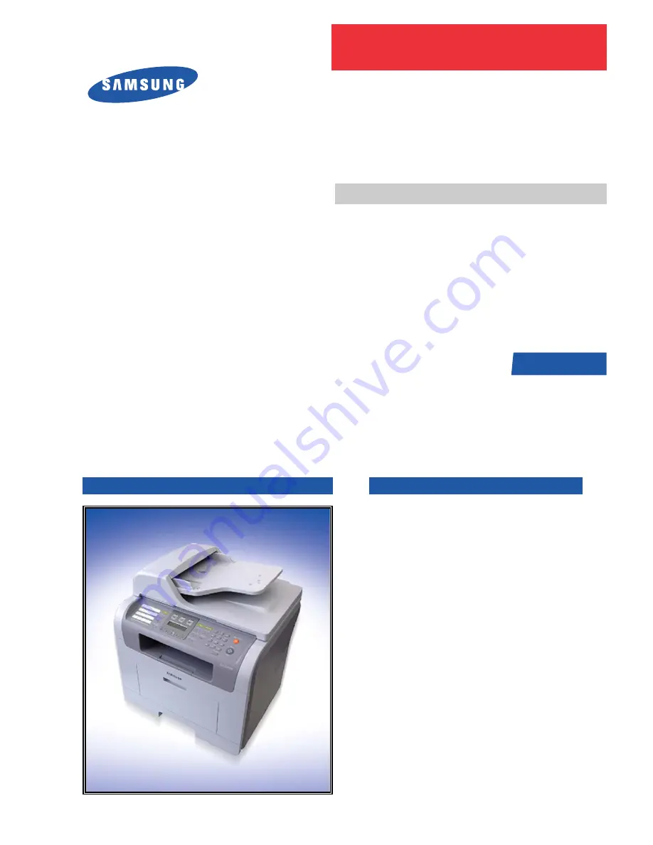
background image

DIGITAL LASER PRINT

The keynote of Product
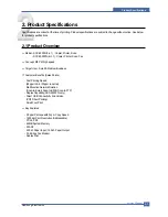
[Key Features]

- 28 ppm Print speed/20 cpm Copy Speed

(Printing Speed: A4/28ppm,Letter/30ppm)

- 1200 dpi Print Resolution (Addressable)

- PCL6, PS3(SCX-5530FN)

- CPU: Chorusm

- Network Solution: Scan-to-Email, Scan-to-SMB,

Scan-to-FTP

- 64MB System Memory/32MB DIMM(5530FN)

- 50 ADF / MP 50 Sheet

- 250 sh Paper Input / 150 sh Paper Output

- 33.6 Kbps Fax Modem (5530FN only)

- Duplex Print (5530FN only)

- Direct USB Connectivity 2nd Version 

(PDF Direct Printing) (5530FN only)

- Small Foot Print

- Toner: 4K(Initial)/ 8K(sales)

Manual

SERVICE

DIGITAL LASER MFP
SCX-5X30 Series

SCX-5

5

30

F

N/

XAZ

Basic Model : SCX-5530FN

Summary of Contents for SCX 5530FN - Multifunction Printer/Copy/Scan/Fax

Page 1: ...etwork Solution Scan to Email Scan to SMB Scan to FTP 64MB System Memory 32MB DIMM 5530FN 50 ADF MP 50 Sheet 250 sh Paper Input 150 sh Paper Output 33 6 Kbps Fax Modem 5530FN only Duplex Print 5530FN only Direct USB Connectivity 2nd Version PDF Direct Printing 5530FN only Small Foot Print Toner 4K Initial 8K sales Manual SERVICE DIGITAL LASER MFP SCX 5X30 Series SCX 5530FN XAZ Basic Model SCX 5530...

Page 2: ...ison Table 2 7 3 System Overview 3 1 System Construction 3 1 3 2 Mechanical Parts Specifications 3 8 3 3 Engine F W 3 31 3 4 S W Descriptions 3 34 4 Alignment and Adjustments 4 1 Paper path 4 1 4 2 Clearing Paper Jams 4 2 4 3 User Mode 4 8 4 4 Tech Mode 4 14 4 5 Identify Sale Date 4 23 4 6 Consumables and Replacement Parts 4 24 4 7 Abnormal Image Printing and Defective Roller 4 25 4 8 Display LED ...

Page 3: ... 12 6 5 Fax Phone Problems 6 19 6 6 Copy Problems 6 23 6 7 Scanning Problems 6 25 6 8 Toner Cartridge Service 6 26 6 9 Network Problems Troubleshooting 6 30 7 Exploded Views Parts List 7 1 Main Exploded Views 7 2 7 2 Cover Ass y 7 4 7 3 Middle Cover Ass y 7 6 7 4 Front Cover Ass y 7 8 7 5 Rear Cover Ass y 7 10 7 6 Frame Assembly 7 12 7 7 Fuser Drive Ass y 7 16 7 8 Main Drive Ass y 7 18 7 9 MP Ass ...

Page 4: ...agram 10 1 Schematic Main 10 1 10 2 DIMM board 10 16 10 3 CRUM board 10 18 10 4 OPE_3in1 10 19 OPE_4in1 10 20 10 5 HVPS 10 21 10 6 SMPS_V1 10 24 SMPS_V2 10 25 10 7 SCF 10 26 10 8 ADF PBA 10 28 10 9 Modem 10 29 10 10 Connection 10 33 10 11 Terminal 10 34 11 Power Signal 11 1 Main Board Power signal 11 1 11 2 OPE ADF Power signal 11 2 11 3 HVPS Voltage map 11 3 ...

Page 5: ...Continued 12 Reference Information 12 1 Tool for Troubleshooting 12 1 12 2 Acronyms and Abbreviations 12 2 12 3 The Sample Pattern for the Test 12 3 12 4 Wireless LAN 12 4 ...

Page 6: ...any human access to laser radiation above a Class I level during normal operation user maintenance or prescribed service condition Warning Never operate or service the printer with the protective cover removed from Laser Scanner assembly The reflected beam although invisible can damage your eyes When using this product these basic safety pre cautions should always be followed to reduce risk of fir...

Page 7: ... or removing the power connector The power connector must be inserted com pletely otherwise a poor contact could cause overheating possibly leading to a fire When removing the power connector grip it firmly and pull 7 Take care of the power cable Do not allow it to become twisted bent sharply round corners or other wise damaged Do not place objects on top of the power cable If the power cable is d...

Page 8: ...rry out the following procedures before dismantling the printer or replacing any parts 1 Check the contents of the machine memory and make a note of any user settings These will be erased if the mainboard or network card is replaced 2 Ensure that power is disconnected before servicing or replacing any electrical parts 3 Disconnect printer interface cables and power cables 4 Only use approved spare...

Page 9: ... you can get harm 3 When you move the printer This printer weighs 17 5kg including toner cartridge and cassette Use safe lifting and handling techniques Use the lifting handles located on each side of the machine Back injury could be caused if you do not lift carefully 4 Ensure the printer is installed safely The printer weighs 17 5Kg ensure the printer is installed on a level surface capable of s...

Page 10: ...ctrical charges sufficient to damage ESDs 5 Do not use Freon propelled chemicals When sprayed these can generate electrical charges sufficient to dam age ESDs 6 Do not remove a replacement ESD from its protective packaging until immediately before installing it Most replacement ESDs are packaged with all leads shorted together by conductive foam aluminum foil or a compa rable conductive material 7...

Page 11: ... Printer Scan Fax Concept MFP of high speed Target User Small Medium Business Customer Benefits Sales Points Fast Printing Speed 28ppm in A4 30ppm in Letter Multifunction Network Solution Scan to Email Scan to SMB Scan to FTP Duplex Capability SCX 5530FN only Direct USB Connectivity 2nd Version PDF Direct Printing Small Foot Print Key Features 28 ppm Print speed 20 cpm Copy Speed 1200 dpi Print Re...

Page 12: ...ion Sleep Mode Less than 30W Power Switch Yes Power Supply Input Voltage Low Voltage 110 127VAC High Voltage 220 240VAC Input Frequency 50 60Hz 3Hz Noise Printing 54dBA Copy 55dBA Standby 39dBA Warm Up Time from Cold Status Less than 20 seconds Cold warm Up time 25sec Machine Life Max Monthly Print 25 000 pages Volume Duty Cycle Scan 2 000 pages ADF 3 000 pages Machine Life 250 000 pages Periodic ...

Page 13: ...0 through ADF Gray Approx 20sec USB 2 0 Color Approx 30sec USB 2 0 Scan Speed Linearity Approx 15sec USB 2 0 through Platen Gray Approx 20sec USB 2 0 Color 75dpi Approx 30sec USB 2 0 300dpi Resolution Optical 600 1200dpi 75 300 600dpi horizontal Enhanced 4800dpi 4800dpi Halftone 256level for only optical resolution Scan Size Max Document Width Max 216mm 8 5 Scan Size Effective Scan Width Max 208mm...

Page 14: ...Copies Special Copy N up copy 2 up 4 up ADF only Special Copy Auto Fit Copy Yes Platen only Special Copy AID Copy Yes Platen only Copy 2 side printed original document into one page ex ID Card Copy Special Copy Clone Yes Platen only Poster Yes Platen only TELEPHONE Handset N A No On hook Dial N A Yes Search N A Yes Phone Book by using Phone Book Button Same as Rocky 1 Touch Dial N A 30EA Speed Dia...

Page 15: ...r Fax N A Yes Sending Only ECM N A Yes Resolution Fine N A 203 196dpi S Fine N A 203 196dpi Std N A 300 300dpi Scan Speed ADF Std N A 2 5 sec LTR Fine S Fine N A 5 sec LTR Rx fax duplex print out N A No Multiple page scan speed N A 21ppm LTR Std mode Receive Mode N A Fax TEL Ans Fax DRPD Memory Capacity N A 8MB Optional N A No Max locations N A 229 locations to store to 1 Group Dial Fax Forward N ...

Page 16: ... Oficio ISO B5 JIS B5 Paper Size MP Tray A4 A5 A6 Letter Legal Folio Oficio Executive ISO B5 JIS B5 3 x5 Monarch No 10 DL C5 C6 Paper Weight Main Tray 16 24lb 60 to 90g MP Tray 16 43 lb Paper Path Standard output Bottom to Middle Front FIFO StraightThrough Face up Single Sheet Paper Size Max 216 x 356mm 8 5 x14 Min 76 x 127mm 3 x5 ADF Paper Weight 12 5 28lb Capacity 50 sheets Document 142mm 216mm ...

Page 17: ...2 3 Model Comparison Table Sec Sec ACCESSORY Item Code Quantity Product Specifications Samsung Electronics Service Manual 2 7 ...

Page 18: ...Options p Item Option Spec Samsung Electronics Service Manual Product Specifications 2 8 Product Specifications 2 6 ...

Page 19: ...for Embedded Applications PVC Dual Single Beam LVDS Pad VDO HSYNC Support A3 1200dpi multi pass color HPVC Dual Single Beam LVDS Pad VDO HSYNC Support A4 600dpi multi pass color DMA 6 Channels if not use CIP4e 4ch is available for external DMA if CIP4E used a4 DMA channel use 2ch available for external DMA Operation Frequency CPU Core over 300MHz System Bus 100MHz Operation Voltage Core Voltage 1 ...

Page 20: ...f exit sensor on the HVPS and actuator on the frame Paper detects the on off time of exit sensor by reading D22 of CPU and the normal operation or jam information is informed to the CPU The paper JAM2 is informed LED will be displayed RED color 5 Cover Open Sensing The Cover open sensor is located on the HVPS After the front cover is opened 24VS DC fan Solenoid Main Motor Polygon motor part of LSU...

Page 21: ...3 1 3 Assembly Description 3 1 3 1 Feeding Section Feeding Method Universal Cassette Type Feeding Standard Center Loading Feeding Capacity Cassette 250 Sheets 75g 20lb StandardPaper 3 1 3 2 Transfer Ass y In Warranty Life time Within 70 000 sheets printing ...

Page 22: ... 3 4 Fuser Ass y Fusing Type Halogen Lamp R2 E Coil type Elbert Halogen Lamp Dove Heat Roller 28 3 with 0 1 Clown Pressure Roller electrically conductive Thermistor Temperature Detecting Sensor Thermostat Overheat Protection Device Trouble Temperature Control concept Open Heat Error 90 below for 45 sec at Warm up Over Heat Error 230 over for 10 sec or 240 over for 5 sec Low Heat Error Standby 130 ...

Page 23: ...nc is generated When the rotation of poygon motor is steady it is time of LSU ready status for printing If either of two condition is not satisfied LSU error is expected 3 1 3 6 Scanner ADF 3 in 1 SCX 5330N 4 in 1 SCX 5530FN Scanning Method Color CCD 600 x 1200 dpi Scan speed SDMP 28cpm MDSP 20cpm Trouble Failure Analysis Polygon Motor Error No steady rotation of Polygon Motor Hsync Error In spite...

Page 24: ...w 3 6 3 1 3 7 Toner Cartridge OPC Cleaning Mechanical Cleaning by the cleaning blade The recycled toner Trash room for the recycled toner No shutter for protecting the OPC Drum Cleaning Roller Cleaning Blade 200V 1 35KV VDC 380V 1 2 3 4 5 6 7 8 4 2kV ...

Page 25: ...ectronics Service Manual 3 7 3 1 3 8 Duplex Unit Duplex printing function as factory option Available Paper Letter Oficio Legal Folio and A4 3 1 3 9 Optional Tray SCF For customer covenience in managing paper Capacity 250 sheets ...

Page 26: ...sette Friction Pad Type MP Friction Pad Type Driver Type Driving by Gearing from Main Motor Pick_up Roller Driver Solenoid Pick up Roller Rubber Material EPDM IR 1 6 or more Pick up Velocity 217 27mm sec Process 179 7mm sec Paper detecting Sensor Photo Sensor Paper Size Sensor None Paper Separating Pad Material NBB 52 0 8 1 2 Separating Pad Pressure 190 gf Pick_up Roller RPM 139 71 RPM Feeding Pre...

Page 27: ...lysis Ni Coating Life Span Print over 70 000 sheets in 15 30 3 2 4 Driver Ass y 3 2 4 1 Motor Spec BLDC 62 PM 55 Motor 2 2 Bipolar PM 42 Motor 2 2 Bipolar Pull Out Torque BLDC 62 1500 gf cm based on actual value or more 1342 4rpm 1 8A PM 55 1490gf cm based on actual value or more 711pps 0 9A PM 42 240gf cm based on actual value or more 1850pps 0 6A TORQUE MARGIN Tp o Tsys BLDC 62 Motor 1500 1100 g...

Page 28: ...217 27mm sec 21 72 VS OPC Vp Feeder cassette 182 34 mm sec 2 15 VS OPC Vp Feeder Frame 180 42 mm sec 1 08 VS OPC Vp Transfer 183 02 mm sec 2 53 VS OPC Vp Fuser 177 96 mm sec 0 3 VS OPC Vp Jitter Horizontal 3 0 022 or less in Vision System Orthogonality SPEC 1 0 mm or less 3 2 4 3 Acoustic Noise Warming Up 49dB or less Printing 54dB or less Copying 55dB or less Stand by 39dB or less ...

Page 29: ... Non Contact type THERMOSTAT Control Temperature 70 5 THERMOSTAT ROLLER Gap 1 1 0 2mm 3 2 5 3 Temperature Detecting Sensor Thermistor Thermistor Type FS 50003 SEMITEC 364FL Type Temperature Resistance 7 180 SYSTEM Temperature SETTING Stand by 165 5 Printing 189 5 5 minutes before 184 5 5 minutes after Overshoot 200 less Overheat 210 less 3 2 5 4 Heat Roller Length 254mm Valid length 224mm OD 28 3 ...

Page 30: ... 6 Media Separating System Thflon Coating with SUS Plate Claw System 3 2 5 7 Safety Relevant Facts Proteciong device when overheating 1st protecting device H W cuts off when detecting an overheating 2st protecting device S W cuts off when detecting overheating 3st protecting device Thermostat cuts off the power Safety device The power of Fuser is cut off after front cover is open The overheating s...

Page 31: ...n Spot Size Main 75 20 20 beam diameter at the level of 1 e2 of intensity at the spot location of 0 100 of image height Variation 40 50 main sub within image height of 100 100 range LaserProperty Wavelength 785 10 15 at 25 Power 0 33 0 02 at the center of image on the focal plane with stationary condition power supplied at DC 5 volt Vignetting Min 80 spot power variation within image height of 100...

Page 32: ...ircuit of polygon motor Starting current Max 2 0 A required current for acceleration Running current Max 1 0 A required current to stable rotational speed Scanning Effective scanning width 216 Property Scanning freq 2 122 44 one line scanning frequency Scanning time 471 15 Scanning dot 5 102 dots 1 dot ON time 53 86 time interval from falling 0 9VH to rising again 0 9VH Scanning effective 58 3 Vid...

Page 33: ...ning blade FILM OPC Handling of wasted toner Collect the wasted toner in the cleaning frame by using cleaning blade OPC Drum Protecting Shutter None Classifying device for toner cartridge ID is classified by interruption of the frame channel 3 2 7 2 Developing Roller Rotary Speed 203 06 mm sec Roller Bias 220V 400 20V Control Type Bias PWM Control type Structure Mono layer Valid Length 228 mm OD 1...

Page 34: ...tem Overview 3 16 3 2 7 5 CHARGING PORTION Type Conductive Roller Contact Charge Rotary Velocity 179 7 mm sec Length 230 mm OD 12 0 0 05 mm Shaft OD 6 0 0 05 mm Driver Gear Driver Roller life 8 000 sheets or more Roller Voltage 1 25 1 70 KV ...

Page 35: ...ement Solution and is roughly composed of two kinds Chip Solution CX86710 SFX336 Existing Modem Chip which adds SSD System Side Device for interfacing between LSD and DIB of FM336Plus Core CX20493 LSD LIU Line Interface Unit Chip which is controlled by SSD and satisfies each PSTN Requirements by modulating internal Configuration with connecting Tel Line ...

Page 36: ... 0 bit deletion ITU CRC 16 or CRC 32 check sum error detection FSK flag pattern detection during high speed receiving Tone modes and features Programmable single or dual tone generation DTMF receiver Tone detection with three programmable tone detectors Receive dynamic range 0 dBm to 43 dBm for V 17 V 29 V 27 ter and V 21 Channel 2 9dBm to 43 dBm for V 34 half duplex Digital speaker output to moni...

Page 37: ...ransformer transfer Clock by separating Primary and Secondary and amplifies Clock Level to LSD by Coil Turns Ratio 1 1 16 Clock Clock is supplied by transformer from SSD to LSD and there is PWROUT to adjust output impedance of Clock Out Driver is inside SSD and CLKSHIGH Resistor to adjust duty of HLPWR Resistor and Clock Clock from SSD to LSD has Differential structure of 180 phase difference for ...

Page 38: ...m Line Code Color Black ON HOOK state Characteristic 1 DC Resistance DP Dial Mode Direct Current 30mA 50 300ohm DTMF Dial Mode Direct Current 20mA 50 540ohm 2 Ring Sensitivity Ring detection Voltage 40Vrms 150Vrms condition Current 25mA Frequency 15Hz product Margin 30Vrms 150Vrms Ring detection Frequency 15 3Hz 68Hz condition Voltage 45Vrms Current 25mA product Margin 15Hz 70Hz Ring detection Cur...

Page 39: ...later Scan Image Control Specification Minimum Scan Line Time 0 7062ms Scan Resolution Max 600DPI Scan Width 216mm main function Internal 12bit ADC White Shading Correction Gamma Correction CCD Interface 256 Gray Scale 3 CCD Operating Part CCD Image sensor use 5V and Inverter uses 24V CCD Maximum Operating Frequency 10MHz CCD Line time 0 7062ms White Data output Voltage 0 7V 0 5V Mono Copy 0 75ms ...

Page 40: ...rcuits of the motor paper feed pass driving clutch driving pre transfer lamp driving current driving and fan driving The signals from the paper feed jam sensor and paper empty sensor are directly inputted to the main board Printing Method Laser based Electro photography Supported Operating Systems Windows 98 2000 NT4 0 ME XP MAC English only no status monitor web download only Emulation SPL GDI PC...

Page 41: ...used a4 DMA channel use 2ch available for external DMA HPVC Dual Single Beam LVDS Pad VDO HSYNC Support A4 600dpi multi pass color PVC Dual Single Beam LVDS Pad VDO HSYNC Support A3 1200dpi multi pass color UART 5 Channels Channel0 supports DMA interrupt Operation INTERRUPT 6 External Interrupts 26 Internal Interrupts TIMER 6 System Timers CIP4e 300 400 600 1200dpi CIS CCD image sensor interface C...

Page 42: ...Hardware Rotator Scaler Halftoner support Engine Controller LSU Interface unit contained APC function Step Motor 4 Phase PWM 8 Channels ADC 8 Channels BLDC clock support APC DAC 2 ea I2C Controller I2C bus SM bus Slave Device Support I2C Version 2 1 RTC RTC Core Voltage 3V PLL 2 PLL MAIN H PVC ...

Page 43: ...System Overview Samsung Electronics Service Manual 3 25 ...

Page 44: ...0 x 300 dpi default User selectable via Content button Text Photo 600 x 300 dpi Photo 600 x 600 dpi Supported Media Types Plain Label Cardstock Transparency Copy Speed Platen SDMP 30cpm Letter SDMP Single Document ADF SDMP 30cpm Letter Multiple Printout ADF MDSP 20cpm A4 Text or Text Photo MDSP Multiple Document 10cpm A4 Photo Single Printout Reduce Enlarge Platen 25 400 1 increments ADF 25 100 1 ...

Page 45: ...oltage Output Voltage Control Method Transfer Output Voltage is outputted and controlled by changing Duty of THVPWM Signal 10 Duty 650V 90 Duty 5KV 5 Charge Voltage MHV Input Voltage 24 V DC 15 Output Voltage 1 3KV 1 8KV DC 50V Output Voltage Rising Time 50 ms Max Output Voltage Falling Time 50 ms Max Output Loading range 30 M 1000 M Output Control Signal MHV PWM CPU is HV output when PWM is Low C...

Page 46: ...wer for driving the system and the AC heater control part which supplies the power to fuser SMPS has two output channels Which are 5V and 24V AC Input Input Rated Voltage AC 220V 240V AC 110V 127V Input Voltage fluctuating range AC 198V 264V AC 99V 135V Rated Frequency 50 60 Hz Frequency Fluctuating range 47 63 Hz Input Current Under 4 0Arms 2 0Arms But the status when e coil is off or rated volta...

Page 47: ...6 4V 4 Max Output Current 3 A 4 4 A 5 Peak Loading Current 3 6 A 5 3 A 1ms 6 RIPPLE NOISEVoltage 100mVp p Under 500mVp p 7 Maximum output 15W 105 6W 8 Peak output 18W 127 2W 1ms 9 Protection for loading Shut down or Fuse Shut down or Output shortage and Protection Voltage Drop overflowing current NO ITEM System 1 Stand By Less than 150W 2 PRINTING Less than 400W 3 Sleep Mode Less than 11W Fuse 5V ...

Page 48: ...coil gets heat from AC power The AV power controls the switch with the Triac a semiconductor switch The ON OFF control is operated when the gate of the Triac is turned on off by Phototriac insulting part In other words the AC control part is passive circuit so it turns the heater on off with taking signal from engine control part When the HEATER ON signal is turned on at engine the LED of PC501 Ph...

Page 49: ...t fed After picking up paper entered but it cannot reach to the feed sensor in certain time due to slip etc After picking up if the feed sensor is not on re pick up After re picking up if the feed sensor is not on after certain time it is JAM 0 It is a status that the leading edge of the paper doesn t pass the feed sensor Even though the paper reaches to the feed sensor the feed sensor doesn t be ...

Page 50: ... is broken out the engine stops all functions and keeps it at the error state Also the engine informs the error status of the main system And then the error message is displayed at LCD window or LED informing the error status of the user Over Heat Error For overall engine state if the temperature of the fixing unit is higher than the specified temperature and the temperature state is kept during t...

Page 51: ... the error state Also the engine informs the error status of the main system and the error message is displayed at LCD window to inform the error status of the user By Hsync When the polygon motor is ready the LSU sends out the signal called Hsync and used to synchronize with each image line So if the engine does not detect consecutively the signal for a fixed time it defines the Hsync Error If th...

Page 52: ...can understand and transfers data to spooler 3 Stand alone Application that offers the various printing application DMS Document Management System RCP Remote Control Panel Printer Status Monitor Network Management in Window system 4 Web based Application that offers the same functions as Stand alone Application and RDC Remote Diagnosis Control in Web environment Firmware is made up of 1 Applicatio...

Page 53: ...functions management of printing job printer administration Status monitor to monitoring the printer status by real time in Web independent environment on OS 3 Stand alone Application that is a similar Window software as same as above 2 4 Port Monitor that manages the network communication between spooler and Network Interface Card or various additional application and Network Interface Card this ...

Page 54: ... USB port Kernel receives this data from Host and then select emulation fit to data and start selected one After emulation job end Kernel sends the output bit map data to Engine using Printer Video Controller by clock type for LSU Engine print the received data to required paper with the sequential developing process 2 Case of using Network Interface Card After user start to print the wanted docum...

Page 55: ...ent and Adjustments This chapter describes the main functions for service such as the product maintenance method the test output related to maintenance and repair DCU using method Jam removing method and so on It includes the contents of manual 4 1 Control Panel 4 1 1 SCX 5530FN ...

Page 56: ...Alignment and Adjustments 4 2 Samsung Electronics Service Manual Alignment and Adjustments 4 2 4 1 2 SCX 5330N ...

Page 57: ... Service Manual 4 2 Paper path Scanner Part Engine Part Roller Heat Roller Exit Roller Exit Roller Transfer Roller Pickup Roller Feed Roller Feed Roller MP Roller Pressure Roller REGI OPC Duplex Duplex Roller REGI OPC Roller ADF Roller Pickup 4 3 ...

Page 58: ...ally paper can be jammed during a print job Some of the causes include The tray is loaded improperly or overfilled The tray has been pulled out during a print job The front cover has been opened during a print job Paper was used that does not meet paper specifications Paper that is outside of the supported size range was used If a paper jam occurs the Jam status will be displayed on LCD panel Find...

Page 59: ...am Caution To avoid tearing the paper pull out the jammed paper gently and slowly Follow the instructions in the following sections to clear the jam 1 scanner lid 1 4 3 3 In the tray 1 1 Open and close the front cover The jammed paper is automatically ejected from the machine If the paper does not exit go to the next step 2 Pull the tray 1 open 3 Remove the jammed paper by gently pulling it straig...

Page 60: ...does not move when you pull or if you do not see the paper in this area stop and go to step 3 3 Pull the tray 1 half 4 Pull the paper straight up and out 5 Insert the trays back into the machine Printing auto matically resumes 4 3 5 In the multi purpose tray 1 If the paper is not feeding properly pull the paper out of the machine 2 Open and close the front cover to resume printing ...

Page 61: ...toner cartridge and close the front cover Printing automatically resumes 4 3 7 In the paper exit area 1 Open and close the front cover The jammed paper is automatically ejected from the machine 2 Gently pull the paper out of the output tray If you do not see the jammed paper or if there is any resistance when you pull stop and go to the next step 3 Open the rear cover 4 If you see the jammed paper...

Page 62: ... to the right open the fuser door 8 Pull the jammed paper out If the jammed paper does not move when you pull push the pressure lever on each side up to loose the paper and then remove it 9 Return the lever door stopper and guide to their orig inal position 10 Close the rear cover Printing automatically resumes 1 rear cover stopper 2 rear cover 2 1 1 pressure lever 1 1 duplex guide 1 1 fuser lever...

Page 63: ...ke sure that the duplex unit is inserted correctly Duplex Jam 0 1 Pull the duplex unit out of the machine 2 Remove the jammed paper from the duplex unit If the paper does not come out with the duplex unit remove the paper from the bottom of the machine Duplex Jam 1 1 Open the rear cover 2 Unfold the duplex guide fully 3 Pull the jammed paper out 1 duplex unit 1 1 1 duplex guide ...

Page 64: ...t Mode Power Save Scan PWR Save Timeout NetScanTimeout Job Timeout Import Setting Export Setting System Setup continued Paper Setup Paper Size Paper Type Paper Source Sound Volume Key Sound Alarm Sound Speaker Ringer Report Maintenance Clean Drum Remote Service Ignore Toner Supplies Life Serial Number Clear Setting Network TCP IP EtherTalk NetWare Ethernet Speed Wireless WLAN Basic WLAN Security W...

Page 65: ...buttons to move the cursor under the digit you want to correct and enter a new number 5 To select AM or PM for 12 hour format press the or button or any number button When the cursor is not under the AM or PM indicator pressing the or button immediately moves the cursor to the indicator You can change the clock mode to 24 hour format e g 01 00 PM as 13 00 For details see the next section 6 Press O...

Page 66: ... the telephone line through the speaker such as a dial tone or a fax tone With this option set to Comm which means Common the speaker is on until the remote machine answers You can adjust the volume level using On Hook Dial Ringer Adjusts the ringer volume For the ringer volume you can select Off Low Mid and High Speaker ringer key sound and alarm sound 1 Press Menu until System Setup appears on t...

Page 67: ... 2 To enter additional letters repeat step 1 If the next letter is printed on the same button move the cursor by pressing the right Scroll button and then press the button labeled with the letter you want The cursor will move to the right and the next letter will appear on the display You can enter a space by pressing 1 twice 3 When you have finished entering letters press OK Keypad letters and nu...

Page 68: ...chine Setup appears 3 Press the Scroll buttons until Power Save appears and press OK 4 Press the Scroll buttons until On appears and press OK 5 Press the Scroll buttons until the time setting you want appears and press OK 6 Press Stop Clear to return to Standby mode Scan Power Save mode Scan Power Save mode allows you to save power by turning off the scan lamp The scan lamp under the scanner glass...

Page 69: ...ror occurs while processing data from the computer and the data flow stops the machine waits the specified time and then cancels printing if data flow does not resume 1 Press Menu until System Setup appears on the bottom line of the display and press OK 2 Press OK when Machine Setup appears 3 Press the Scroll buttons until Job Timeout appears and press OK 4 Press the Scroll buttons until the time ...

Page 70: ...perations To enter the Tech mode To enter the Tech mode press in sequence and the LCD briefly displays TECH the machine has entered service tech mode 4 5 2 Setting up System in Tech Mode SCX 5530FN Send Level DTMF Level Pause Time Dial Mode Modem Speed Error Rate RDS Clear All Mem Clear Counts Flash Upgrade Silence Time Switch Test Modem Test Dram Test Rom Test Pattern Test Shading Test All Report...

Page 71: ...ow the set value You can select the rate between 5 and 10 CLEAR ALL MEMORY The function resets the system to factory default settings This function is used to reset the system to the initial value when the product is functioning abnor mally All the values are returned to the default values and all the information which was set by the user will be erased Method 1 Select the MEMORY CLEAR at the TECH...

Page 72: ...or upgrade Save the files in the same folder 2 In the DOS input as below and push the enter key Then it will be automatically upgraded 3 There are two commands for the conditions of product When the product is in idle condition down rom file When the product is in Ready condition TECH MODE DATA SETUP FLASH UPGRADE LOCAL copy b rom file lpt1 4 Do not turn off the power while upgrading process 2 Rem...

Page 73: ...res all of the Copy Setup options to the factory default Fax Setup Restores all of the Fax Setup options to the factory default Fax Feature Cancels all of the scheduled fax jobs in the machine s memory As below item you can selectively clear information stored in your machine s memory Advanced Fax Restores all of the Advanced Fax setting options to the factory default Sound Volume Resets the sound...

Page 74: ...upgrade Save the files in the same folder 2 In the DOS input as below and push the enter key Then it will be automatically upgraded 3 There are two commands for the conditions of product When the product is in idle condition down rom file When the product is in Ready condition TECH MODE DATA SETUP FLASH UPGRADE LOCAL copy b rom file lpt1 4 Do not turn off the power while upgrading process 3 2 Remo...

Page 75: ...enter the new password TECH MODE DATA SETUP NOTIFY TONER RDS RDS Password 7 If you are to enable the RDS system Notify Toner option should be Off 4 3 Call setup Release In order to perform any RDS activity on a Customer MFP the SVC will have to setup a call to it On successful completion of call setup one or more RDS functions can be executed before call release is manually initiated When connecti...

Page 76: ...is feature to test the machine S ROM The result and the software version appear in the LCD display FLASH VER 1 00 V ENGINE VER 1 00V PATTERN TEST Using this pattern printout you can check if the printer mechanism is functioning properly It is needed in the production progress Service person doesn t need to use it SHADING TEST The function is to get the optimum scan quality by the specific characte...

Page 77: ...p 3 T 30 protocol during the most recent sending or receiving operation Use this list to check for send and receive errors If a communication error occurs while the machine is in TECH mode the protocol list will print automatically OTHER ITEM This list provides a list of the user system data settings and tech mode settings Component Check ...

Page 78: ... Unit is ready to print On the other case Laser Error 13 LD Test Diode On is displayed when the laser diode is on Diode On Off On the other case Diode Off is displayed 21 Feed Sen Test These Functions are considered to check the present Sensor Off to Sensor On 22 Exit Sen Test state normal or not of the Sensors 23 Cover Sen Test After the cover is open touch the sensor and confirm Cover Open to Co...

Page 79: ...chine it will start a scan and page count The time the machine was first used is remembered These settings are are remembered after memory delete Clear All Memory Method Press MENU 1 9 3 in sequence Firmware version is displayed on LCD Press 1 in the number keypad The LCD display shows Updated date Press 2 in the number keypad The LCD display shows Product first use date Display OS 1 00 86 07 11 3...

Page 80: ...e example list is for an average usage of 50 transmitted and received documents per day Environmental conditions and actual use will may vary The cycle period given below is for reference only COMPONENT REPLACEMENT CYCLE ADF Rubber Pad 20 000 Pages ADF Roller 60 000 Pages Pick up Roller 150 000 Pages Transfer Roller 70 000 Pages Fuser 80 000 Pages Tray Rubber Pad 150 000 Pages ...

Page 81: ...75 5mm White spot Block spot 2 Charge Roller 37 7mm Black spot 3 Supply Roller 53 2mm Horizontal density band 4 Develop Roller 39 2mm Horizontal density band 5 Transfer Roller 47 1mm Black side contamination transfer fault 6 Heat Roller 88 9mm Black spot and fuser ghost 7 Pressure Roller 101 3mm Black side contamination 1 2 3 4 OPC Drum Charge Roller Supply Roller Developing Roller 5 6 7 Transfer ...

Page 82: ...s Service Manual Alignment and Adjustments 4 28 4 9 Display LED and Error Messages 4 9 1 Display LED The Status LED on the control panel shows the status of your machine See the table below to know your machine s status ...

Page 83: ...ndicate the machine s status or errors Refer to the tables below to understand the messages meaning and correct the problem if necessary Messages and their meanings are listed in alphabetical order Note When you call for service it is very convenient to tell the service representative the display mes sage Messages in the colored cells are available only with SCX 5530FN ...

Page 84: ...Samsung Electronics Service Manual Alignment and Adjustments 4 30 ...

Page 85: ...Alignment and Adjustments Samsung Electronics Service Manual 4 31 ...

Page 86: ...Samsung Electronics Service Manual Alignment and Adjustments 4 32 ...

Page 87: ...Alignment and Adjustments Samsung Electronics Service Manual 4 33 ...

Page 88: ...Samsung Electronics Service Manual Alignment and Adjustments 4 34 ...

Page 89: ...machine note the cable routing that will be affected Whenever servicing the machine you must perform as follows 1 Check to verify that documents are not stored in memory 2 Be sure to remove the toner cartridge before you disassemble parts 3 Unplug the power cord 4 Use a flat and clean surface 5 Replace only with authorized components 6 Do not force plastic material components 7 Make sure all compo...

Page 90: ...the ADF Ass y 2 Apply light pressure to the left side of the Cover Upper Left and pull it in the direction of arrow as shown below 3 Apply light pressure to the right side of the Cover Upper Right and pull it in the direction of arrow as shown below ADF Ass y 1 2 Cover Upper Right 2 1 Cover Upper Left ...

Page 91: ... Front Cover 1 Take out the Cassette 2 Open the Cover 3 If necessary remove the Toner Cartridge 4 To remove the Front Cover first pull the part below the both side of the Front Cover with a light pressure to the direction of arrow Cassette Toner Cartridge Front Cover 2 1 ...

Page 92: ... 1 Open the MP Tray Ass y 2 Pull the Tray Links from the both side of the Front Cover with a light pressure to the direction of arrow 3 Apply light pressure to the both side of the MP Tray Ass y and pull it in the direction of arrow as shown below MP Tray Ass y MP Tray Ass y Tray Link ...

Page 93: ... four screws securing the Rear Cover and then Release the Rear Cover from the Set 3 To remove the Face Up Cover first release the Stopper Strap in the direction of arrow 4 Unlatch the Face Up Cover from the Rear Cover and then release the Face Up Cover as shown below Duplex Unit Stopper Strap 1 2 Rear Cover Face Up Cover ...

Page 94: ...the Thermostat and then remove the three screws securing the Thermostat and remove it 4 To remove the Electrodes first release REC Harness from the left side of the Electrode and then release the CON Harness from the right side of the Electrode as shown below 5 Remove the two screws securing the both side of the Electrode and then release the Caps and Electrodes in the direction of arrow as shown ...

Page 95: ...lug the connector from the Input Guide and remove the one screw securing the Thermistor and remove it 8 Remove the three screws securing the Idle Gear Bracket and remove it 9 Remove the three screw securing the Fuser Cover and release the Fuser Cover from the Fuser Frame Input Guide Idle Gear Bracket Thermister Fuser Cover Fuser Frame ...

Page 96: ...at Roller 11 To remove the Guide Input first unlatch the Hook and then release the Guide Input in the direction of arrow as shown below Notice You must remove the Guide Input before removing the Jam Holder so that you won t damaged Pressure Roller 12 Remove the Jam Link Lever L R and Jam Holder L R and then remove the Pressure Roller as shown below Heat Roller HR Bush HR Bush Hook 1 2 Guide Input ...

Page 97: ...ght Side Cover as shown below 3 Apply light pressure to the bottom of the Right Side Cover and pull it to the right side in the direction of arrows as shown below 4 Remove the two screws securing the Left Side Cover as shown below 5 Apply light pressure to the bottom of the Left Side Cover and pull it to the left side in the direction of arrows as shown below 5 7 Side Cover Left Right Left Side Co...

Page 98: ...sung Electronics Service Manual Disassembly and Reassembly 5 10 6 To remove the DIMM Cover first open the DIMM Cover in the direction of arrow and then release the DIMM Cover as shown below DIMM Cover 2 1 ...

Page 99: ...R Refer to 5 2 2 Remove the two screws securing the OPE Unit to the Platen Ass y 3 Apply light pressure to the front of the OPE Unit and pull it in the direction of arrow as shown below 4 Unplug the three connectors from the OPE PBA as shown below 5 Remove the nine screws securing the OPE PBA to the OPE Cover LCD Cover OPE PBA OPE Cover OPE Unit ...

Page 100: ...ers from the OPE Cover 7 Remove the Lens and Keys from the OPE Cover 8 If necessary remove the NEVI Cover 9 For easy disassembly release the Battery NIH LED Lens Onetouch FAX Menu Mode Copy Tel On Hook Start Black Stop Clear Black Battery NIH Onetouch Menu Tel_Copy Mode NEVI Cover Sheet Label ...

Page 101: ...irst remove the seven screws securing the ADF Engine part to the Cover Platen and then release the ADF Engine part in the direction of arrow as shown below Notice Take care to thread the ADF Harness through the Cover Platen 4 Remove the Open Cover as shown below Notice When working on the ADF Motor Ass y take care not to contaminate any of the rubber surfaces with grease 5 9 ADF Ass y ADF Ass y AD...

Page 102: ...art take great care to note the position of the Ferrite Core and the Motor Harness routing When refitting the ADF Engine part ensure that the Harness and Ferrite are properly located and are clear of the Motor Fan and White Bar Clip 7 Unplug the two connector and remove four screws securing the ADF Motor Ass y and then remove the receptacle of the Ground Cable as shown below Then take out the ADF ...

Page 103: ... Unit Refer to 5 8 ADF Ass y Refer to 5 9 2 Remove the two screws securing the Platen Ass y as shown below 3 Remove the one screw securing the Ground Cable and unplug the four connectors and CCD Cable 4 Lift the Platen Ass y in the direction of arrow as shown below 5 Remove the four screws securing the Scan Upper 5 10 Platen Ass y Platen Ass y ADF Ground Cable ...

Page 104: ... shown below 7 Remove the CCD Cable as shown below Notice You should connector remove the CCD Cable vertically to avoid the CCD Cable pin damage 8 Pull up the CCD Shaft and take out the CCDM 9 Squeeze the spring to release the tension in the Belt and lift from the pulleys as shown below Scan Upper Scan Lower CCD Cable Core CCDM CCD Shaft Belt Spring ...

Page 105: ...e the two screws securing the Scan Motor and remove it as shown below 12 To remove the ADF Lower Harness first unlatch the Hooks in the direction of arrow and then carefully release the ADF Lower Harness from the Scan Lower as shown below 13 Unplug the connector from the Open Sensor Ass y Scan Motor Ass y Scan Motor Gear Bracket Ass y ADF Lower Harness 1 2 1 ...

Page 106: ...r and release the CCD Home Sensor as shown below Caution Reassembling CCDM 1 When refitting the Scanner Belt and Belt Spring take care to relocate the tension spring as close to the right side of the CCDM as is possible as shown below 2 When refitting the Scan Upper Cover take care to ensure that the Cover Open Switch is not trapped Sensor Lever Open Sensor CCD Holder CCD Home Sensor Harness ...

Page 107: ...uring the Shield Controller Ass y and remove it 4 Remove the five screws securing the Main PBA to the Shield and unplug the Film Cable and then remove the Main PBA 5 The connectors are located as shown below 5 11 Shield Controller Ass y Shield Controller Ass y Shield Film Cable Main PBA ADF Flat Motor Flat Cover CCD OPE Panel USB Host Cartridge USB Port Modem PBA Duplex Motor Engine BLDG Pick Up R...

Page 108: ... three screws securing the Modem PBA to the Shield and unplug the Film Cable and then remove the Modem PBA 7 Remove the two screws securing the Speaker to the Shield and unplug the connector from the Modem PBA and then remove the Speaker Modem PBA Shield Film Cable Shield Speaker ...

Page 109: ...y and remove it Notice The six screws have numbers stamped into the Drive Ass y base plate When refitting the Drive Ass y tighten the screws the order they are numbered Only screws numbered 1 to 5 are fitted at this stage Screw 6 is fitted when the Shield Controller Ass y is refitted 3 If necessary remove the four screws securing the BLDC Motor Ass y and remove it 5 12 Drive Ass y Drive Ass y Gear...

Page 110: ...s y you should remove Side Cover Right Refer to 5 7 3 2 Unplug the connector from the Connection PCB and remove the three screws securing the Duplex Drive Unit and remove it 3 If necessary remove the two screws securing the Duplex Motor and remove it Duplex Drive Ass y Connection PCB Duplex Motor Harness Duplex Motor Bracket Ass y ...

Page 111: ...ight Refer to 5 7 3 Duplex Drive Ass y Refer to 5 13 2 Unplug the two connectors HVPS Fuser 3 Remove the three screws securing the Shield SMPS Ass y and remove it 4 Unplug the connector AC Inlet and remove the four screws securing SMPS and remove it HVPS Connector Fuser Connector Shield SMPS Ass y SMPS Insulator Sheet Shield SMPS With AC Inlet AC Inlet Connector ...

Page 112: ...u remove the Connection PCB you should remove Side Cover Right Refer to 5 7 3 2 Unplug the all connectors 3 Remove the two screws securing the Connection PCB and remove it 4 The connectors are located as shown below Connection PCB Connection PCB Fuser Exit Motor Duplex Fan FAN MAIN HVPS Duplex Motor ...

Page 113: ...e Cover Right Refer to 5 7 3 2 Unplug the connector from the Connection PCB 3 Remove the three screws securing the Fuser Drive Ass y and remove it 4 If necnsary remove the two screws securing the Step Motor and remove it Fuser Drive Connection PCB Fuser Drive Ass y Step Motor Harness Fuser Exit Bracket Ass y 5 16 Fuser Drive Ass y ...

Page 114: ...ve the Fan you should remove Side Cover Right Refer to 5 7 3 2 Unplug the two connectors from the Connection PCB as shown below 3 Remove the two screws securing the Fans and then pull the Fans Main Duplex 5 17 Fan Main Fan Duplex Fan Fuser Exit Motor Connection PCB Duplex Fan Main Fan ...

Page 115: ...n slide the Pick Up Roller Ass y from left to right and it will be released completely as shown below 3 To remove the Shaft first release the locker and slide the Shaft from left to right then lift the notch attached to the Cam so that it s released from the Shaft Then release the Bush from the Shaft and remove the Shaft from the Duplex Guide Housing as shown below 2 1 Cam Bush Shaft Locker 3 4 Ca...

Page 116: ...fer to 5 18 2 Remove the two screws securing the Duplex Guide Housing 3 Unplug the one connector Photo Interrupter and remove the Duplex Guide Housing with Feed Roller as shown below 4 Pull the Feed Roller from the Bushing Duplex Guide Housing Bushing Feed Roller 5 19 Duplex Guide Housing With Feed Roller Photo Interrupter Connector Duplex Guide Housing ...

Page 117: ...r to 5 14 Pick Up Roller Ass y Refer to 5 18 Duplex Guide Housing Refer to 5 19 2 Remove the eight screws securing the HVPS Housing as shown below 3 Unplug the connector for connector PBA and SMPS first Unplug the other Connections 4 If necessary remove the three screws securing the HVPS and remove it HVPS Housing Duplex Motor Connection PBA SMPS Engine Duplex Guide Housing HVPS Insulator Sheet Sh...

Page 118: ...Mid Front Hook Hook Samsung Electronics Service Manual Disassembly and Reassembly 5 30 5 21 Middle Cover Ass y 1 Before you remove the Middle Cover Ass y you should remove Side Cover Left Right Refer to 5 7 Scanner Ass y Refer to 5 10 Shield Controller Ass y Refer to 5 11 2 Remove the six screws securing the Middle Cover Ass y and remove it 3 If necessary remove the two screws securing the USB Hos...

Page 119: ... remove it 3 To remove the MP Pick Up Ass y first lift the notch attached to the left side Stopper so that it s slide the right to left from the Shaft then left side Idle slid the right to left from the Shaft and take out the MP Pick Up Ass y as shown below Notice Do not grab the rubber part of the Feed1 Roller it may cause a malfunction due to a foreigen object MPF Housing Stopper 1 2 Idle MP Pic...

Page 120: ... 21 MPF Housing Refer to 5 23 2 Remove the two screws securing the both side of the Plate Push Bushing and then remove the Guides 3 Pull up the Feed Idle Shaft and the Bushs with Spring 4 Release the E Ring securing the Feed2 Gear and remove it 5 Remove the three screws securing the Feed Bracket Unit and then remove the Feed Bracket Unit and Feed2 Shaft Plate Push Bushing Feed Idle Shaft Bush Spri...

Page 121: ...racket as shown below Notice Be aware of the E Rings to ensure they are not lost 7 Remove the Clutch Unit as shown below 8 Pull up the Feed1 Roller from the Bushing as shown below Notice Do not grab the rubber part of the Feed1 Roller it may cause a malfunction due to a foreigen object T2 Idle Gear Retard Gear Idle Gear E Ring Bracket Feed Shaft Feed1 Gear Ass y Clutch Unit Feed1 Roller ...

Page 122: ...Roller it may cause a malfunction due to a foreigen object 5 26 Exit Roller 1 2 1 Exit Gear Roller Exit F Down Exit Roller Rack Bearing 1 Before you remove the Pick Up Gear Ass y Solenoids you should remove Duplex Guide Housing Refer to 5 19 Feed Bracket Unit Refer to 5 24 5 2 Release the Pick Up Gear Ass y and Pick Up Gear Shaft as shown below 3 Remove the two screws securing the Manual Solenoid ...

Page 123: ...ur screws securing the LSU and remove it LSU 5 27 LSU 1 Before you remove the CRUM2 PBA you should remove Middle Cover Ass y Refer to 5 21 LSU Refer to 5 27 2 Remove the one screw securing the CRUM2 PBA and remove it and then release the four Terminals as shown below Notice Be aware of the Terminals to ensure they are not lost CRUM2 PBA Terminal 5 28 CRUM2 PBA ...

Page 124: ...oller first pull the TR Holder and then take out the Transfer Roller as shown below Notice Do not grab the rubber part of the Transfer Roller it may cause a malfunction due to a foreigen object Hole the both side of the Transfer Roller when replacing it TR Holder 2 1 5 29 Transfer Roller Parts ...

Page 125: ...pting to repair the printer first obtain a detailed description of the problem from the customer Power On No Power Power Module error Main PBA error LCD Panel error Refer to Solution of Image Problem OP Panel ON Ready or Power save Indicate Error Massage Refer to Error Massage Chapter 4 8 Test Print END printing Quality is Nomal ...

Page 126: ... PR CR DR SR TR FR Empty Sensor OPC Fuser Toner Cartridge EXIT Sensor Feed Sensor MP Sensor Check and Cause Solution 1 Check the Solenoid by using Engine Test Mode 2 Check the surface of the roller pick up for foreign matter 3 If continuous clusters occur check whether the assembly slot between shaft pickup and housing pickup become open or is broken away 4 If the paper feeds into the printer and ...

Page 127: ...deformed Check if the lever part is deformed in shape Check whether burrs occur in the assembly part of the actuator exit or not and if the actuator is smoothly operated Check if foreign matters and wire get caught in the actuator exit s operation 2 If the paper is stuck in the fuser dis assemble the fuser and remove the jammed paper and clean the surface of the pressure roller with dry gauze 3 Re...

Page 128: ... 3 Use the smooth paper 6 2 6 Paper rolled in the fuser Description Paper rolled in the fuser 100 5mm Check and Cause Solution 1 Contamination of the pressure roller or heat roller Background Hot off set 2 Check the claw of the fuser whether it is deformed 1 After disassembling the fuser clean contamination between the heat roller and the thermostor and remove the contamination of the pressure rol...

Page 129: ...urning the OPC against the ongoing direction Clean fingerprints on the OPC softly with soft cloth dampened with IPA Isopropyl Alcohol or tis sue 6 2 8 Defective ADF Description ADF Automatic document Feeder is not properly operated Check and Cause Solution 1 Check if ADF rubber and HOLDER rubber are dam aged 2 Check if the document sensors of ADF Ass y 3 paper sensors are normal 1 Replace the cont...

Page 130: ...ly 1 Try again after clearing the memory 2 After confirming that OPE HARNESS is connected to the Connection B d correctly if it is so then replace the OPE Ass y and Main Board in sequence 6 3 2 Defective LCD Operation Description Defective LCD Operation Check and Cause Solution 1 Clear the memory 2 Confirm to catch a click sound while a key on the OPE panel is pressed on 1 The key is wrong itself ...

Page 131: ...hen paper is loaded in the cassette Check and Cause Solution 1 Bending or deformation of the actuator of the paper sen sor 2 The function of the Main PBA is defective Perform Engine Test Mode 1 Replace the defective actuator 2 Replace the Main PBA 6 3 5 Paper Empty without indication Description The paper empty status on the operator panel does not come on when the paper cassette is empty Check an...

Page 132: ...itch department in the Main PBA 1 Replace the hook lever if defective 2 Check the insertion of the Door Open S W Connect 3 Replace the Main PBA or Door Open S W 6 3 7 No Beep on when the Door is open Description Door open status does not come on even when the printer Door is open Check and Cause Solution Check the Connector CN1 and Circuit of the Cover Switch department in the Main PBA 1 Check the...

Page 133: ...Check the Motor operation 1 Check the Motor harness replace it if defective 2 Replace the SMPS if necessary 6 3 9 No Power Description When system power is turned on all lamps on the operator panel do not come on Check and Cause Solution 1 Check if the power input and SMPS output are normal 2 Check for defective of LCD Panel on the front cover if the LCD of Panel does not appear after normal warmi...

Page 134: ... Vertical Line Getting Curved Description When printing vertical line gets curved Check and Cause Solution 1 If the supply of 24v is unstable in the Main Control board linking with LSU check drive by Engine Test Mode 1 Replace LSU 2 Replace the Main Control board ...

Page 135: ...it 3 Check an operation of a feed roller and a registration roller If they are worn or defective replace them 4 Replace a Duplex unit 6 3 11 Duplex Jam 1 Description A message Duplex Jam 1 is displayed in a LCD window Check and Cause Solution 1 It is a case when a paper can not operate a duplex sensor 2 It is a case when a paper can not reach to a duplex sensor due to a paper jam on a duplex path ...

Page 136: ...igital Printer Check and Cause Solution 1 Foreign matter stuck onto the window of internal lenses of LSU mirror 2 Foreign matter or toner particles between the developer roller and blade In case the life of the developer has been expired white lines or light image occur in front of the image 3 It may occur when a Burr and foreign substances are on the window of the developer frame 4 If the fuser i...

Page 137: ...inter Digital Printer Digital Printer Digital Printer Digital Printer Check and Cause Solution 1 If dark or blurry black spots occur periodically the rollers in the Developer may be contaminated with foreign matter or paper particles Charge roller 37 7 mm interval OPC drum 75 5 mm interval 2 If faded areas or voids occur in a black image at intervals of 75 5 mm or black spots occur elsewhere the O...

Page 138: ...d try to print out 3 No 2 Wait 30 minutes after printer is pow ered on before you start printing 4 No3 Clean up the contaminated area by the toner 5 Replace the HVPS if the problems are not solved by the above four directions 6 4 6 Dark Image or a Black Description The printed image is dark Digital Printer Digital Printer Digital Printer Digital Printer Digital Printer Check and Cause Solution 1 N...

Page 139: ...lade 1 Replace both the left and right Spring Holder 2 Problem with the toner cartridge replace the toner cartridge and try to print out 6 4 8 Background Description Light dark background appears in whole area of the printing Digital Printer Digital Printer Digital Printer Digital Printer Digital Printer Check and Cause Solution 1 Recycled recording paper has been used 2 The life of the Developer ...

Page 140: ...the contaminated terminals 2 Problem in the toner cartridge replace the toner cartridge and try to print out 3 Replace the engine board if not solved by the above directions 1 2 4 If not solved by the direction 3 check the transfer roller lifetime and replace it 5 Wait about 1 hour after power on before using printer 6 Problem in the toner cartridge replace the toner cartridge and try to print out...

Page 141: ...lPrinter DigitalPrinter DigitalPrinter DigitalPrinter DigitalPrinter DigitalPrinter 77 8 mm Check and Cause Solution The temperature of the fuser is maintained high 1 Disassemble the fuser and remove the contaminated toner particles on the roller and clean the foreign matter between Thermistor and Heat roller Caution can be deformed 6 4 13 Stains on the front of the page Description The background...

Page 142: ...formed 6 4 15 Blank Page Print out 1 Description Blank page is printed Digital Printer Digital Printer Digital Printer Digital Printer Digital Printer Check and Cause Solution Bad ground contacts in OPC and or devel oper Remove contamination of the terminals of the toner cartridge and the printer 6 4 16 Blank Page Print out 2 Description 1 Blank page is printed 2 One or several blank pages are pri...

Page 143: ...s y may be defective Try to replace the OPE Ass y 3 Check the Speaker connection and try to replace it 4 Lastly try to replace the Main B d 6 5 2 Defective MF DIAL Description The MF DIAL is not functioning Check and Cause Solution 1 Check if the telephone line is connected correctly 2 Wile the BUTTON KEY is pressed check to catch a CLICK sound 3 Check the connection of HARNESS between the LIU and...

Page 144: ...eplace the LIU B d 2 If the MODEM testing is abnormal try to replace the Main B d 6 5 4 Defective FAX FORWARD Description RECEIVE is functioning but FORWARD is not functioning or the received data are broken Check and Cause Solution 1 Check if there is NOISE when pressing on hook dial 2 Check the RECEIVE condition by trying to forward a FAX to another fax machine from the forwarding side FAX 3 Che...

Page 145: ...when pressing on hook dial 2 Ask to the forwarding side check the image quality of another machine receiving a FAX additionally sent to 1 If it makes NOISE rearrange the telephone line Refer to Defective FAX RECEIVE 2 Check if the FAX status of the forwarding side is also normal Check and Cause Solution Check if the RECEIVE Mode is TEL MODE or FAX MODE Even when the RECEIVE Mode is changed to FAX ...

Page 146: ...not working Check and Cause Solution Check the FAX status of the forwarding side After checking the data of the forwarding side correct the FAX of the forwarding side Check and Cause Solution 1 Check if the RECEIVE Mode is TEL MODE or FAX MODE 1 If the RECEIVE Mode is set to the TEL MODE reset it to the FAX MODE 2 Even after the RECEIVE Mode is changed to the FAX Mode it cannot receive then try to...

Page 147: ...e 3 Check white black reference voltage in Main PBA 1 Room light ca transit a thin original 2 Remake shading profile in the tech mode 3 Replace U60 if it is defective U60 154 0 5V U60 155 3 3V 6 6 2 Black Copy Description Black page is printed out when Copy Check and Cause Solution 1 Check the CCD problem in Main PBA 2 Check shading profile 1 Check the CCD harness contact 2 Remake shading profile ...

Page 148: ...mage is light or bad Check and Cause Solution 1 Check shading profile 2 Check the gap between original and scanner glass 3 Check printing quality 1 Remake shading profile in the tech mode 2 The gap above 0 5 mm can cause a blurred image 3 See Print troubleshooting 1 Check the right position of the Scanner Motor and check the any mechanical disturbance in the CCD carriage part 2 If any driver is de...

Page 149: ...inting test related to driver setup if it is not so rein stall it Refer to User s Manual 3 If copy function works replace the Main PBA If copy function doesn t work replace the CCD Ass y and try again 6 7 2 Defective Image Quality of PC Scan Description The image PC scanned is not clear or bad Check and Cause Solution 1 Check the waveform form by performing a CCD test in TECH Mode 2 Check if the r...

Page 150: ...ar the end of its life white streaks or light print occurs The LCD displays the warning mes sage Toner Low You can temporarily reestablish the print quality by redistributing the remaining toner in the cartridge 6 8 3 Service for Judgement of Inferior Expendables and the Standard of Guarantee Please refer to User s Manual or Instructions on Fax Printer Expendables SVC for the judgement of inferior...

Page 151: ...of the falling of the toner 2 Check the appearance of both ends of the developer OPC drum 2 The center of the printed mat ter is contaminated with toner 1 Check whether foreign sub stances or toner are stuck to the terminal contact point of the developer 2 Check whether the state of the terminal assembly is normal 1 All of 1 2 3 above 1 The weight of the developer ended 800g 20g 2 If it become bet...

Page 152: ... and rough printouts 1 Check whether foreign sub stance or toner are stuck to the terminal contact point of the developer 2 Check whether the state of the terminal assembly is normal 1 In case of 1 above Run OPC Cleaning Mode Print 4 5 times repeatedly to remove Especially check foreign sub stance on the OPC surface then remove them with a clean gauze moistened with IPA Isopropyl Alcohol not to da...

Page 153: ...check the charged roller terminal 3 The printed image is dark and ghost occurs 1 Check foreign substance attached to the terminal point of contact of the developer and the state of assembly Especially check the devel oping roller terminal 1 All of 1 2 3 above 1 Remove toner and foreign sub stances adhered to the contact point of the developer 2 The contact point of the unit facing that of the deve...

Page 154: ...tThru If ping succeeds verify that community names with sufficient permissions have been used Check the environment as described in Auto Detection of Print Server Check NetWare file server consoles for error messages regarding nodes with conflicting network numbers On Network Interface in SyncThru you should set Static to IPAddress Assignment Method in TCP IP tab You should set IP address Subnet M...

Page 155: ...er in SyncThru The print server name is displayed but the test page is not printed Firmware upgrade process is completed But upgrading is not executed 1 Verify that the printer power switch is turned on and the READY message is displayed on the printer front panel 2 Verify that the LAN cable is plugged into the PortThru card 3 Verify that the second LED on the PortThru card blinks If the second LE...

Page 156: ...e same LAN If LAN is connected by routers SyncThru is unable to detect the printers In this case one of protocols which are enabled in NPC should be Installed in the computers 4 In case that the protocol which is enabled in NPC is installed in the computers If TCP IP installed check entry values of IP address subnet mask and default gateway Try Add a Port 6 9 4 SyncThru Installation Problems Probl...

Page 157: ...odem 5530FN only Duplex Print 5530FN only Direct USB Connectivity 2nd Version PDF Direct Printing 5530FN only Small Foot Print Toner 4K Initial 8K sales 7 1 Main Exploded Views 7 2 7 2 Cover Ass y 7 4 7 3 Middle Cover Ass y 7 6 7 4 Front Cover Ass y 7 8 7 5 Rear Cover Ass y 7 10 7 6 Frame Assembly 7 12 7 7 Fuser Drive Ass y 7 16 7 8 Main Drive Ass y 7 18 7 9 MP Ass y 7 20 7 10 Scan Ass y 7 22 7 11...

Page 158: ...Samsung Electronics Service Manual Exploded Views Parts List 7 2 7 1 Main Exploded Views 0 14 23 7 6 25 16 17 3 1 15 2 34 26 27 5 4 4 1 4 2 4 3 28 30 31 8 1 8 2 8 24 33 12 11 10 13 9 13 1 13 2 32 29 ...

Page 159: ...AR TRANSFER 1 SA 7 1 9 JC63 00912A SHIELD P CONTROLLER 1 SA 7 1 10 3001 001293 SPEAKER 1 SA 7 1 11 JC92 01746A PBA SUB MODEM 1 SA 7 1 12 JC39 00518A CBF HARNESS ENGINE 1 SA 7 1 13 JC96 03970A ELA HOU MAIN RAM DIMM 1 SA 7 1 13 1 JC92 01743A PBA MAIN CONTROLLER 1 SA 7 1 13 2 JC92 01836A PBA SUB SDRAM 1 SA 7 1 14 JC96 03773A ELA HOU ADF 1 SA 7 1 15 JC97 02391A MEA COVER 1 SNA 7 1 16 JC96 03795A ELA U...

Page 160: ...Samsung Electronics Service Manual Exploded Views Parts List 7 4 7 2 Cover Ass y 0 1 2 2 3 2 1 2 2 3 4 5 5 1 5 2 6 7 8 ...

Page 161: ..._SUB ACTUATOR 1 SNA 7 2 2 3 JC72 01339A PMO M SUB ACTUATOR 1 SNA 7 2 3 JC96 03793A ELA HOU COVER MID 1 SA 7 2 4 JC63 00928A COVER M_SIDE R 1 SA 7 2 5 JC97 02417A MEA COVER SIDE L 1 SA 7 2 5 1 JC63 00929A COVER M_SIDE L 1 SNA 7 2 5 2 JC63 00930A COVER M_DIMM 1 SNA 7 2 6 JC97 02418A MEA COVER REAR 1 SA 7 2 7 JC63 00934A COVER M_LEFT UPPER 1 SA 7 2 8 JC63 00933A COVER M_RIGHT UPPER 1 SA Drawer SEC_Co...

Page 162: ...Samsung Electronics Service Manual Exploded Views Parts List 7 6 7 3 Middle Cover Ass y 0 1 2 3 4 5 6 6 ...

Page 163: ...SA 7 3 1 JC63 00927A COVER M_MIDDLE 1 SA 7 3 2 JC63 00944A COVER M_STACKER RX 1 SA 7 3 3 JC92 01636A PBA SUB USB HOST 1 SA 7 3 4 JC39 00397A CBF HARNESS USB HOST 1 SA 7 3 5 JC63 00938A COVER M_REAR UPPER 1 SA 7 3 6 JC72 01001A PMO SUB STACKER 2 SA Drawer SEC_Code Description QT y Service SA SERVICE AVAILABLE SNA SERVICE not AVAILABLE ...

Page 164: ...Samsung Electronics Service Manual Exploded Views Parts List 7 8 7 4 Front Cover Ass y 0 1 2 3 4 5 6 6 7 8 9 10 11 ...

Page 165: ...A SPRING ETC CIS C2 1 SA 7 4 4 JC64 00154C KNOB M_LOCKER 1 SA 7 4 5 JC63 00447E TRAY M ASF_FOLDER 1 SA 7 4 6 JC63 00444A TRAY M LINK_MP 2 SA 7 4 7 JC63 00945A TRAY M ASF_INPUT 1 SNA 7 4 8 JG66 40003A GEAR PINION 1 SA 7 4 9 JC70 00479D ADJUST M_MP R 1 SNA 7 4 10 JC70 00478D ADJUST M_MP L 1 SNA 7 4 11 JC63 00446E TRAY M ASF_INPUT UPPER 1 SA Drawer SEC_Code Description QT y Service SA SERVICE AVAILAB...

Page 166: ...Samsung Electronics Service Manual Exploded Views Parts List 7 10 7 5 Rear Cover Ass y 0 1 2 3 7 4 5 9 6 8 9 8 9 8 9 8 ...

Page 167: ...H DELL 1 SNA 7 5 3 JC63 00936A COVER M_FACE UP 1 SNA 7 5 4 JC61 00962A PLATE MAGNET CATCH 1 SNA 7 5 5 JC63 00937A COVER M STACKER REAR 1 SNA 7 5 6 JC61 01653A STOPPER M STRAP 1 SNA 7 5 7 JC61 01583A GUIDE OUTPUT FUSER 1 SNA 7 5 8 JC61 00785A HOLDER M IDLE ROLLER 4 SNA 7 5 9 JC72 40981A PMO ROLLER UPPER DP 4 SNA Drawer SEC_Code Description QT y Service SA SERVICE AVAILABLE SNA SERVICE not AVAILABLE...

Page 168: ... 3 8 4 8 5 13 10 1 10 2 10 3 6 1 6 2 6 3 6 4 7 1 7 2 7 3 3 1 3 2 3 3 3 4 3 5 3 6 3 7 3 9 1 3 9 1 3 9 2 3 9 3 3 10 3 11 3 12 3 8 15 5 5 5 4 16 17 17 18 19 20 21 22 23 24 25 26 27 27 28 29 30 31 67 32 33 34 32 35 36 36 1 36 2 36 3 36 4 39 40 41 42 43 44 45 46 47 48 52 52 1 53 54 55 56 57 58 59 60 Transfer Roller 0 62 62 49 50 51 61 68 73 72 71 70 69 74 ...

Page 169: ...USHING_P U MP 1 SA 7 6 3 12 JC66 00050A CAM CATCH 1 SA 7 6 3 13 JC66 01173A ROLLER FEED 1 SA 7 6 4 JC66 00527A SHAFT FEED IDLE 1 SA 7 6 5 JC61 00585A BUSH M FEED IDLE 3 SA 7 6 6 Not ssign FEED1 ASS Y 1 SNA 7 6 6 1 JC61 01619A HOLDER M_ACT REGI 1 SA 7 6 6 2 6107 001164 SPRING TS 2 SA 7 6 6 3 JC66 01189A LEVER M_ACTUATOR FEED 1 SA 7 6 6 4 JC66 01191A LEVER M_ACTUATOR REGI 1 SA 7 6 7 Not ssign FEED2 ...

Page 170: ...CABLE CLAMP 1 SNA 7 6 27 JC61 70932A SPRING ETC GUIDE DEVE 1 SA 7 6 28 JC72 00984A PMO PLATE GUIDE DEVE_L 1 SA 7 6 29 JC72 00985A PMO PLATE GUIDE DEVE_R 1 SA 7 6 30 JC63 00926A GROUND P SHIELD 1 SNA 7 6 31 JC65 00019A TERMINAL P_CRUM 4 SA 7 6 32 JC61 00829A HOLDER BEARING EXIT F DOWN 2 SA 7 6 33 JC97 01034A MEA RACK EXIT ROLLER 1 SA 7 6 34 JC66 01196A ROLLER EXIT F DOWN 1 SNA 7 6 35 JC92 01829A PB...

Page 171: ...LATE P PUSH BUSHING 1 SNA 7 6 55 JC61 00907A HOLDER M PTL R2 1 SA 7 6 56 JC70 00307A IPR P EARTH TRANSFER 1 SA 7 6 57 JC61 00047A SPRING ETC TR L HAWK 1 SA 7 6 58 JC61 00588A BUSH M TR L 1 SA 7 6 59 JC72 00102A PMO BUSHING_TR L 1 SA 7 6 60 JC63 00918A GROUND P EARTH TR 1 SNA 7 6 61 JC96 03790A ELA HOU FRAME 110V 1 SA 7 6 61 JC96 03789A ELA HOU FRAME 220V 1 SA 7 6 62 JC61 00835A FOOT BACK 2 SA 7 6 ...

Page 172: ...Samsung Electronics Service Manual Exploded Views Parts List 7 16 7 7 Fuser Drive Ass y 0 1 2 3 4 4 5 6 7 8 9 ...

Page 173: ...R EXIT 1 SNA 7 7 2 JC31 00037E MOTOR STEP MAIN 1 SA 7 7 3 JC66 01158A GEAR EXIT RDCN 87 24 1 SNA 7 7 4 6044 000231 RING E 2 SA 7 7 5 JC66 01163A GEAR FUSER RDCN IN 95 1 SNA 7 7 6 JC66 00340A GEAR HUB CLUTCH 1 SA 7 7 7 JC66 00417A GEAR RDCN FUSER OUT 1 SA 7 7 8 JC66 01210A GEAR FUSER IDLE FR 1 SA 7 7 9 6044 000125 RING E 1 SA Drawer SEC_Code Description QT y Service SA SERVICE AVAILABLE SNA SERVICE...

Page 174: ...Samsung Electronics Service Manual Exploded Views Parts List 7 18 7 8 Main Drive Ass y 0 1 2 3 4 5 6 8 7 6 7 ...

Page 175: ...SNA 7 8 2 JC66 01156A GEAR OPC RDCN 93 61 1 SNA 7 8 3 JC61 01597A BRACKET P MOTOR MAIN 1 SNA 7 8 4 JC31 00047A MOTOR DC BLDC MAIN 1 SA 7 8 5 JC66 01157A GEAR OPC DRV 113 33 1 SNA 7 8 6 JC66 01162A GEAR FEED RDCN 55 18 2 SNA 7 8 7 6031 000023 WASHER PLAIN 2 SNA 7 8 8 6302 001056 GASKET 1 SNA Drawer SEC_Code Description QT y Service SA SERVICE AVAILABLE SNA SERVICE not AVAILABLE ...

Page 176: ...Samsung Electronics Service Manual Exploded Views Parts List 7 20 7 9 MP Ass y 0 1 2 2 1 2 2 2 3 2 4 2 5 2 6 3 4 5 6 7 8 9 10 11 12 13 14 15 16 17 17 1 17 2 17 3 18 19 20 21 22 23 24 25 26 24 27 ...

Page 177: ...SPRING ETC EXIT ROLL FD 1 SA 7 9 9 JC61 00927A PLATE P KNOCK UP_MP 1 SNA 7 9 10 JC72 00761A PMO ROLLER CAM MP 1 SA 7 9 11 JC73 00141A RPR PAD CASSETTE 1 SA 7 9 12 6107 001237 SPRING ES 2 SA 7 9 13 JC61 00926A HOLDER M SENSOR_MP 1 SA 7 9 14 0604 001095 PHOTO INTERRUPTER 1 SA 7 9 15 JC72 01338A PMO M ACT EMPTY MP 1 SA 7 9 16 JC39 00365A CBF HARNESS MPF SEN 1 SA 7 9 17 JC97 02034A MEA PICK UP_MP 1 SA...

Page 178: ...Samsung Electronics Service Manual Exploded Views Parts List 7 22 7 10 Scan Ass y 0 1 2 3 4 5 7 7 6 ...

Page 179: ...84A ELA HOU ADF LOWER 1 SA 7 10 2 JC96 03773A ELA HOU ADF 1 SA 7 10 3 JC96 03787K ELA HOU OPE 4IN1 1 SA 7 10 4 4302 001183 BATTERY NIH 2ND 1 SA 7 10 5 JC39 00513A CBF HARNESS OPE 1 SNA 7 10 6 3301 001635 CORE FERRITE 1 SNA 7 10 7 6502 000121 CABLE CLAMP 2 SNA Drawer SEC_Code Description QT y Service SA SERVICE AVAILABLE SNA SERVICE not AVAILABLE ...

Page 180: ...s Parts List 7 24 7 11 Platen Ass y 0 1 1 1 1 1 2 1 1 4 1 1 1 1 1 3 1 1 4 1 1 5 1 1 6 1 2 1 5 1 5 1 4 1 3 2 2 2 6 2 2 2 2 5 2 2 4 2 2 3 2 2 2 2 2 1 2 2 7 2 3 2 4 2 5 2 10 2 12 2 11 2 13 2 14 2 9 2 8 2 7 2 6 2 1 2 13 2 15 2 16 1 2 16 2 2 18 2 19 2 21 ...

Page 181: ...069A ELA HOU SCAN MOTOR 1 SA 7 11 2 2 1 JC61 00895A BRACKET SCAN MOTOR R2 1 SA 7 11 2 2 2 JC66 00531A GEAR TIMING 1 SA 7 11 2 2 3 JB72 00764A PMO HOLDER BELT 1 SA 7 11 2 2 4 6044 000125 RING E 1 SA 7 11 2 2 5 JB66 00083A GEAR IDLE 1 SA 7 11 2 2 6 JC66 00530A GEAR REDUCTION73 37 1 SA 7 11 2 2 7 JB31 00011A MOTOR STEP SCAN 1 SA 7 11 2 3 JC96 03819A ELA HOU CCDM_2905 1 SA 7 11 2 4 JB70 00145A ICT SHA...

Page 182: ...Samsung Electronics Service Manual Exploded Views Parts List 7 26 7 12 Cover Platen Ass y 0 1 1 1 1 2 1 3 1 4 1 5 2 3 4 4 5 6 7 7 5 8 9 ...

Page 183: ... 1 SNA 7 12 1 4 JF70 10616A IPR WASHER SPRING CU 2 SA 7 12 1 5 JG66 40003A GEAR PINION 1 SA 7 12 2 JC63 00984A COVER M_PLATEN 1 SNA 7 12 3 JC63 00209A SHEET WHITE SPONGE 1 SNA 7 12 4 JC97 01707A MEA UNIT HINGE 2 SA 7 12 5 JC61 00011A SPRING ETC FEED 6 SA 7 12 6 JF70 40521B ICT SHAFT PINCH 1 SA 7 12 7 JG72 40663A PMO ROLL PINCH 2 SA 7 12 8 JC66 00909A SHAFT IDLE FEED 2 SA 7 12 9 JC66 00728A ROLLER ...

Page 184: ... 1 19 1 17 1 16 1 15 1 13 1 7 1 7 1 11 1 14 1 12 1 1 1 18 1 4 1 5 1 6 1 7 1 8 1 2 1 3 1 7 1 9 1 10 2 1 2 2 2 13 2 3 2 4 2 5 2 15 2 17 2 4 2 5 2 5 2 5 2 4 2 6 2 7 2 19 2 20 2 24 2 24 2 8 2 9 2 7 2 10 2 11 2 25 2 12 2 13 2 14 2 15 2 17 2 18 2 19 2 20 2 21 2 22 4 4 1 4 18 4 2 4 3 4 6 4 4 4 12 4 10 4 11 4 9 4 15 4 5 4 17 4 8 4 8B 4 8A 4 7 4 13 4 14 4 15 4 16A 4 16B ...

Page 185: ... 01010A PMO ACTUATOR REGI SENSOR 1 SA 7 13 1 17 JC72 01320A PMO ACT EMPTY ADF 1 SA 7 13 1 18 JC70 10467A IPR GROUND_ROLLER 1 SNA 7 13 1 19 JC63 00372A GROUND P ADF R2 1 SA 7 13 1 20 JC39 00534A CBF HARNESS ADF R GND 1 SA 7 13 1 21 JC39 00538A CBF HARNESS ADF CLUT1 1 SA 7 13 2 JC96 03783A ELA HOU ADF MOTOR 1 SA 7 13 2 1 JC61 01589A BRACKET P GEAR H 1 SNA 7 13 2 2 JC31 00036A MOTOR STEP ADF 1 SNA 7 ...

Page 186: ...3 4 5 JB70 00168A ICT PIN ADF 2 SA 7 13 4 6 6031 000023 WASHER PLAIN 1 SA 7 13 4 7 JC72 00734A PMO COVER ADF 1 SA 7 13 4 8 JB75 00300A MEC PICK UP ROLLER ASSY 1 SA 7 13 4 8A JB72 00823A PMO SLEEVE PICK UP 1 SA 7 13 4 8B JB73 00055A RMO PICKUP ROLLER 1 SNA 7 13 4 9 JB72 00821A PMO ADF COLAR 1 SA 7 13 4 10 JB61 70904A SPRING ETC CLUTCH 1 SA 7 13 4 11 JB72 00817A PMO ADF CLUTCH 1 SA 7 13 4 12 JB66 00...

Page 187: ...Exploded Views Parts List Samsung Electronics Service Manual 7 31 7 14 OPE Unit 0 2 1 4 3 5 6 7 8 10 9 12 13 14 15 23 11 16 17 18 19 20 21 22 ...

Page 188: ...00244A KEY M_BLACK 2 SNA 7 14 10 JC64 00240A KEY M_COPY 1 SNA 7 14 11 JC64 00241A KEY M_FAX 1 SNA 7 14 12 JC64 00247A KEY M_MODE SCAN 1 SNA 7 14 13 JC64 00245A KEY M_MODE COPY 1 SNA 7 14 14 JC64 00246A KEY M_MODE FAX 1 SNA 7 14 15 JC64 00248A KEY M_MENU 1 SNA 7 14 16 JC64 00250A KEY M_ONETOUCH 1 SNA 7 14 17 JC73 00231A RUBBER ONETOUCH 1 SNA 7 14 18 JC73 00230A RUBBER MENU 1 SNA 7 14 19 JC73 00233A...

Page 189: ...Exploded Views Parts List Samsung Electronics Service Manual 7 33 7 15 Cassette Ass y 0 1 2 3 4 1 4 4 3 4 2 4 4 5 6 7 7 8 9 10 11 12 13 14 15 16 ...

Page 190: ...C73 00140A RPR FRICTION PAD 1 SA 7 15 5 JC61 70911A SPRING ETC EXIT ROLL FD 1 SA 7 15 6 JC61 00603A PLATE P KNOCK_UP 1 SNA 7 15 7 6107 001166 SPRING CS 2 SA 7 15 8 JC73 00141A RPR PAD CASSETTE 1 SA 7 15 9 JC66 00719A CAM M KNOCK UP 1 SNA 7 15 10 JC61 00876A FRAME M_CASSETTE 1 SNA 7 15 11 JC61 00918B GUIDE M EXTENSION L2 1 SA 7 15 12 JC72 00971A PMO EXTENSION SMALL 1 SA 7 15 13 JC72 00972A PMO PLAT...

Page 191: ...ded Views Parts List Samsung Electronics Service Manual 7 35 7 16 Fuser Ass y 1 2 33 35 3 9 4 5 6 7 8 10 11 12 13 14 0 34 34 15 16 17 18 19 18 21 22 23 24 25 26 27 30 28 29 34 31 32 20 2 20 20 3 20 4 20 1 31 ...

Page 192: ...BRACKET P FUSER 1 SNA 7 16 16 JC61 01306A HOLDER M_JAM R 1 SNA 7 16 17 JC61 01305A HOLDER M_JAM L 1 SNA 7 16 18 6044 000125 RING E 2 SA 7 16 19 JC66 00957A LEVER M_LINK JAM 2 SNA 7 16 20 JC96 03803A ELA UNIT HEAT 110V 1 SA 7 16 20 JC96 03804A ELA UNIT HEAT 220V 1 SA 7 16 20 1 JC66 01211A ROLLER HEAT 1 SNA 7 16 20 2 JC66 10901A BEARING PRESSURE R 1 SA 7 16 20 3 JC61 01629A BUSH M_HR R 1 SNA 7 16 20...

Page 193: ...Exploded Views Parts List Samsung Electronics Service Manual 7 37 7 17 Duplex Unit Optional 0 1 2 3 4 9 9 5 6 16 7 3 8 8 5 10 9 9 8 11 12 13 14 15 9 9 ...

Page 194: ...6 JC66 00038A GEAR EXIT F DOWN 1 SA 7 17 7 JC96 03662A ELA UNIT ROLLER_DUP 1 SNA 7 17 8 JC66 00900A PULLEY M 18 DUMMY_DUP 3 SA 7 17 9 6003 000196 SCREW TAPTITE 6 SA 7 17 10 JC65 00017A TERMINAL P GND DUP 1 SNA 7 17 11 JC61 01595A GUIDE M_UPPER DUP 1 SNA 7 17 12 6107 001156 SPRING TS 2 SA 7 17 13 JK72 00058A PCT SILP WASHER 4 SNA 7 17 14 JC66 00896A ROLLER M IDLE_ DUP 1 SA 7 17 15 JC66 00444A SHAFT...

Page 195: ...Ass y 8 5 8 5 ADF Ass y 8 6 8 6 DADF Ass y 8 7 8 7 DADF Platen Cover Ass y 8 8 8 8 DADF SUB Ass y 8 9 8 9 Side Cover Ass y 8 10 8 10 Cassette Ass y 8 11 8 11 Exit Ass y 8 12 8 12 Feeder Ass y 8 13 8 13 MP Ass y 8 14 8 14 Base Frame 8 15 8 15 Pick up Ass y 8 16 8 16 Drive Ass y 8 17 8 17 Main Frame Ass y 8 18 8 18 FuserAss y 8 19 8 19 SCF Unit Option Cassette 8 20 Contents ...

Page 196: ...1 41 3 41 2 40 1 40 2 40 3 40 4 26 1 26 3 26 2 26 4 26 41 50 40 10 48 2 1 2 2 2 1 1 2 0 24 13 30 49 32 38 9 11 OPC DRUM Toner Cartridge 4 3 28 6 12 35 21 2 21 1 21 17 37 44 16 46 45 25 20 39 34 5 15 14 33 47 18 2 19 SCF 51 18 1 8 18 1 1 SCX 6322DN SCX 6122FN 29 29 3 29 2 29 1 7 ...

Page 197: ...Exploded View Parts List Samsung Electronics Service Manual 8 3 8 2 Housing Scanner 0 1 3 2 ...

Page 198: ...8 3 OPE Cover 0 1 2 3 4 11 12 22 21 15 16 17 5 6 7 8 9 10 13 14 20 23 19 18 Exploded View Parts List Samsung Electronics Service Manual 8 4 ...

Page 199: ... 34 7 34 6 34 24 34 5 34 4 34 3 34 22 34 2 34 28 34 1 34 15 34 14 34 11 34 28 34 12 34 13 27 34 26 34 23 34 16 34 17 34 18 34 18 9 34 18 9 34 18 8 34 18 7 34 18 5 34 18 6 34 18 1 34 18 2 34 18 3 34 18 4 34 21 34 20 34 19 34 29 33 33 1 33 3 33 2 33 4 33 2 33 5 33 9 33 8 33 7 33 10 33 6 33 2 3 33 2 2 33 2 1 33 2 4 ...

Page 200: ...Ass y 4 5 4 11 4 7 6 4 4 6 3 9 3 10 3 11 3 12 5 2 2 1 2 2 2 3 2 4 2 5 3 1 3 2 3 22 3 2 3 2 3 3 4 3 4 3 5 3 3 4 2 S1 S1 4 1 4 9 4 3 4 4 4 8 3 14 3 13 3 13 3 7 3 8 3 18 3 19 3 6 3 15 3 17 1 3 21 3 20 0 1 1 1 2 1 4 1 6 1 3 1 5 1 10 1 11 1 4 1 15 1 13 1 9 1 8 7 1 12 7 10 10 8 9 ...

Page 201: ...Exploded View Parts List Samsung Electronics Service Manual 8 7 0 1 2 3 4 5 5 1 5 2 5 3 5 4 5 5 5 6 5 7 5 8 5 9 8 6 DADF Ass y 0 1 2 3 4 5 5 1 5 2 5 3 5 4 5 5 5 6 5 7 5 8 5 9 ...

Page 202: ...8 7 DADF Platen Cover Ass y 0 1 10 2 3 5 7 6 8 9 4 11 10 13 12 Exploded View Parts List Samsung Electronics Service Manual 8 8 ...

Page 203: ...0 2 40 3 0 1 1 2 1 12 1 3 1 1 1 6 1 5 1 4 1 7 1 8 1 9 1 10 1 11 1 14 1 13 1 15 2 3 4 5 6 7 8 9 10 11 11 1 11 2 11 3 11 4 11 5 11 6 11 7 12 13 14 15 16 17 18 19 21 20 26 22 23 41 43 42 24 17 44 27 32 42 31 33 28 29 30 42 17 43 42 34 12 13 15 14 41 36 37 38 39 40 39 1 39 2 39 3 39 4 39 5 39 6 39 7 ...

Page 204: ... Exploded View Parts List 8 10 8 9 Side Cover Ass y 0 1 1 1 1 2 1 3 1 4 1 5 1 6 1 7 1 8 1 8 1 9 1 6 1 10 1 11 1 12 1 12 1 13 1 14 1 15 1 16 1 17 1 18 1 18 1 19 1 20 2 2 1 2 2 2 3 2 5 2 6 2 7 2 8 2 8 2 2 8 3 2 8 4 2 8 5 2 8 6 2 8 1 2 8 7 ...

Page 205: ...8 10 Cassette Ass y 0 3 11 14 13 7 S6 S6 S6 8 16 1 6 10 12 5 15 2 24 22 2 9 21 17 19 20 19 18 Samsung Electronics Service Manual 8 11 Exploded View Parts List ...

Page 206: ...Samsung Electronics Service Manual Exploded View Parts List 8 12 8 11 Exit Ass y 0 14 11 13 10 7 2 1 23 22 21 8 9 12 15 16 18 24 17 6 5 4 3 19 20 ...

Page 207: ...8 12 Feeder Ass y 20 2 17 6 5 3 7 1 4 8 S1 11 21 12 13 17 5 15 19 15 18 12 16 6 9 10 22 22 19 Exploded View Parts List Samsung Electronics Service Manual 8 13 ...

Page 208: ...Samsung Electronics Service Manual Exploded View Parts List 8 14 8 13 MP Ass y 22 16 6 20 18 21 26 20 25 3 25 14 5 10 9 3 1 8 4 2 12 17 24 13 23 11 7 19 15 ...

Page 209: ...8 14 Base Frame 0 18 20 17 19 1 2 21 22 23 14 24 15 16 3 4 5 6 7 8 9 10 11 12 13 Samsung Electronics Service Manual 8 15 Exploded View Parts List ...

Page 210: ...Samsung Electronics Service Manual Exploded View Parts List 8 16 8 15 Pick up Ass y 0 2 1 3 4 6 7 8 9 10 10 1 10 2 11 11 1 12 13 14 15 11 2 5 ...

Page 211: ...8 16 Drive Ass y 0 11 12 13 14 16 15 7 9 8 1 2 3 4 5 31 27 24 25 6 10 26 23 21 22 14 6 20 19 18 17 Exploded View Parts List Samsung Electronics Service Manual 8 17 ...

Page 212: ...Samsung Electronics Service Manual Exploded View Parts List 8 18 8 17 Main Frame Ass y 0 6 3 2 1 5 4 34 33 31 32 21 37 20 19 18 16 15 14 13 12 10 11 38 9 8 7 5 24 22 35 26 25 23 36 27 28 29 30 17 ...

Page 213: ...8 18 Fuser Ass y 0 24 23 22 21 20 19 18 17 16 14 15 13 12 11 10 9 8 7 6 2 1 29 28 27 26 25 5 1 5 2 3 4 Samsung Electronics Service Manual 8 19 Exploded View Parts List ...

Page 214: ...e 6 6 2 2 1 2 8 2 8 S6 S11 S11 2 3 2 2 5 5 8 5 19 5 15 5 9 5 4 6 6 1 6 7 6 5 6 2 6 2 6 4 6 3 6 6 3 9 8 2 5 8 1 8 2 8 3 8 4 S6 S6 S9 S9 8 5 2 6 2 7 2 4 4 1 0 S11 S11 S11 5 1 5 2 5 13 5 13 5 13 5 16 5 10 5 11 5 4 5 5 5 6 5 7 5 17 5 12 5 3 5 14 5 18 5 13 5 4 7 1 7 S9 7 2 S6 S6 S6 S6 S6 S6 S6 S6 S6 ...

Page 215: ...01792D 1 SA 8 1 20 COVER PANNEL MFP JC63 01089C 1 SNA 8 1 21 ELA HOU DUCT FAN JC96 02311A 1 SA 8 1 21 1 FAN DC JC31 00012A 1 SA 8 1 21 2 PMO DUCT FAN JC72 00807A 1 SA 8 1 24 SOLENOID PICK UP JC33 00007A 1 SA 8 1 25 PMO COVER EXIT REAR JC72 00790B 1 SA 8 1 26 MEA UNIT GUIDE CST PA JC97 01624B 1 SA 8 1 26 1 PPR SHEET GUIDE PAPER JC72 00836A 1 SA 8 1 26 2 PMO GUIDE CST RAIL JC72 00791B 1 SA 8 1 26 3 ...

Page 216: ...2 SNA 8 3 8 KEY M_ON HOOK JC64 00249A 1 SNA 8 3 9 KEY M_MENU JC64 00248A 1 SNA 8 3 10 LENS STATUS JC67 00198A 1 SNA 8 3 11 RUBBER TEL JC73 00246A 1 SA 8 3 12 RUBBER MODE JC73 00247A 1 SA 8 3 13 RUBBER MENU JC73 00230A 1 SNA 8 3 14 COVER LCD JC63 01157A 1 SNA 8 3 15 KEY M_MODE SCAN JC64 00247A 1 SNA 8 3 16 KEY M_MODE COPY JC64 00245A 1 SNA 8 3 17 KEY M_MODE FAX JC64 00246A 1 SNA 8 3 18 RUBBER FAX J...

Page 217: ...ARNESS OPE JC39 00340A 1 SA 8 4 34 23 CBF HARNESS SCAN MOTOR JB39 00077A 1 SA 8 4 34 24 CBF HARNESS DRIVER GND JB39 00065A 1 SNA 8 4 34 25 CBF SIGNAL CCD FFC JC39 00236A 1 SA 8 4 34 26 CBF HARNESS SCAN_DSUB JC39 00338A 1 SA 8 4 34 27 ELA UNIT CORE JB96 01381A 3 SA 8 4 34 28 SHAFT CCD UMAX JC66 00532A 1 SA 8 4 34 28 IPR CHANNEL BASE FRAME JC70 00239A 2 SA 8 6 0 ELA HOU DADF JC96 02943B 1 SNA 8 6 1 ...

Page 218: ... WHITE BAR JC70 00225A 1 SA 8 8 7 SPRING ETC WHITE BAR JC61 00548A 2 SA 8 8 8 SHEET GUIDE PAPER JC63 00185A 1 SNA 8 8 9 ROLLER EXIT JC66 00588A 1 SA 8 8 10 GEAR DADF_EXIT31 JC66 00571A 1 SA 8 8 11 MEA UNIT COVER EXIT JC97 01841B 1 SNA 8 8 11 1 COVER EXIT JC63 00196B 1 SNA 8 8 11 2 SPRING ETC WHITE BAR JC61 00548A 2 SA 8 8 11 3 PMO ROLLER IDLE SCAN JC72 00906A 3 SA 8 8 11 4 SHAFT EXIT IDLE JC66 006...

Page 219: ...DUPLEX JC97 01578B 1 SA 8 9 1 1 IPR E PLATE SAW MCK2 JC70 10232D 1 SA 8 9 1 2 IPR BRACKET GUIDE B JC70 00234A 1 SA 8 9 1 3 PMO HOLDER SAW JC72 41213B 1 SNA 8 9 1 4 IPR BRACKET GUIDE A JC70 00229A 1 SA 8 9 1 5 PMO FEED FRAME JC72 00731A 1 SA 8 9 1 6 SPRING ETC FEED JC61 00478A 2 SA 8 9 1 7 PMO BUSHING FEED JC72 00730A 1 SA 8 9 1 8 GEAR DUP IDLER 17 JC66 00341A 3 SA 8 9 1 9 GEAR MP DUP DRV JC66 0034...

Page 220: ...DE EXIT LOWER JC72 00710A 1 SA 8 11 3 SPRING ETC EXIT LOWER IDLE JC61 00484A 4 SA 8 11 4 HOLDER EXIT MC JC61 00547A 4 SNA 8 11 5 PMO ROLLER FD F JC72 41007A 4 SA 8 11 6 PMO ROLLER FD R JC72 41008A 4 SA 8 11 7 SPRING ETC EXIT ROLL FD JC61 70911A 2 SA 8 11 8 SHAFT IDLE_LOWER JC66 00715A 1 SNA 8 11 9 PMO ROLLER_EXIT JC72 40361A 4 SNA 8 11 10 PMO GUIDE_EXIT UPPER JC72 00708B 1 SA 8 11 11 MEC ROLLER EX...

Page 221: ...1 SA 8 13 15 PMO FRAME MP JC72 00770B 1 SA 8 13 17 PMO HOLDER SENSOR MP JC72 00772A 1 SA 8 13 18 PMO HOUSING PICK UP MP JC72 00773A 1 SA 8 13 19 PMO PLATE KNOCK UP MP JC72 00775A 1 SA 8 13 20 PMO IDLE PICK UP MP JC72 41027A 2 SA 8 13 21 RPR RUBBER PICK UP MP JC73 00089A 1 SA 8 13 22 RPR RCT PAD PICKUP MP JC73 00090A 1 SA 8 13 23 PAD MP PLUS JC69 00494A 1 SA 8 13 24 PBA SUB MP SEN JC92 01362A 1 SA ...

Page 222: ...GEAR DEVE DRV JC66 00338A 1 SA 8 16 14 GEAR HUB CLUTCH JC66 00340A 2 SA 8 16 15 PMO DEV COUPLING JC72 00743A 1 SA 8 16 16 GEAR RDCN FEED OUTER JC66 00343A 1 SA 8 16 17 GEAR OPC DRV JC66 00347A 1 SA 8 16 18 MEC BRAKE GEAR JC75 00163A 1 SNA 8 16 19 GEAR OPC 55 31 JC66 00581A 1 SNA 8 16 20 BRACKET P BRAKE JC61 00853A 1 SNA 8 16 21 GEAR FEED DRV JC66 00348A 1 SA 8 16 22 GEAR FUSER DRV INNER JC66 00333...

Page 223: ...70 00064A 3 SNA 8 18 5 MEA UNIT CLAW JC97 01587B 4 SA 8 18 5 1 SPRING ETC SAPERATION JC61 70909A 1 SA 8 18 5 2 PMO GUIDE CLAW JC72 00376B 1 SA 8 18 6 BRUSH CARBON JC67 00067A 2 SA 8 18 7 SPRING CS 6107 001172 2 SA 8 18 8 SCREW MACHINE 6001 000568 2 SNA 8 18 9 COVER M BRUSH JC63 00353A 2 SNA 8 18 10 SCREW TAPTITE 6003 000154 5 SA 8 18 11 ELECTRODE P FRONT JC70 00469A 1 SNA 8 18 12 THERMOSTAT 4712 0...

Page 224: ...Block diagram Service Manual 8 1 Samsung Electronics 8 8 8 Block Diagram ...

Page 225: ...Connection Diagram Service Manual 9 1 Samsung Electronics 9 9 9 Connection Diagram ...

Page 226: ...CD INTERFACE CCD LAMP PWM CONTROLLER 8 F Engineer ENGINE INTERFACE SCF INTERFACE 14 D 10 COMPANY NAME 8 6 Sheet NOR FLASH MEMORY DELAY BUFFER SYSTEM EEPROM B C 2 Index 4 2 MFG ENGR CHK EXIT MOTOR DUPLEX MOTOR FLATEN MOTOR DUPLEX INTERFACE 1 Page Drawn by USB HOST CONTROLLER 6 E 11 Address A 7 of 5 CLK RESET BATTERY CHARGER Changed by Date Changed A 15 3 QA CHK ENGINE INTERFACE FUSER CONTROLLER BLD...

Page 227: ...4 DATA30 U1 DATA31 U2 DATA3_NFCON_IO_3 AC1 DATA4_NFCON_IO_4 AC2 DATA5_NFCON_IO_5 AC3 DATA6_NFCON_IO_6 AC4 DATA7_NFCON_IO_7 AB1 DATA8_NFCON_IO_8 AB2 DATA9_NFCON_IO_9 AB3 DQM0 AD15 DQM1 DATA20 Y4 DATA21 Y5 DATA22 W1 DATA23 W2 DATA24 W3 DATA25 W4 DATA26 W5 DATA27 V2 DATA28 V3 DATA29 V4 DATA2_NFCON_IO_2 AD3 AB4 DATA11_NFCON_IO_11 AB5 DATA12_NFCON_IO_12 AA1 DATA13_NFCON_IO_13 AA2 DATA14_NFCON_IO_14 AA3...

Page 228: ...D_82 K11 GND_9 B6 GND_A B10 GND_PLL_1 D11 GND_PLL_2 B23 GND_RING_1 F20 GND_RING_2 R22 LEVEL_SHIFT_GPIO_17 U13 GND_70 U14 GND_71 U15 GND_72 U16 GND_73 U17 GND_74 V26 GND_75 AB26 GND_76 AF6 GND_77 AF10 GND_78 AF13 GND_79 K10 T11 GND_60 T12 GND_61 T13 GND_62 T14 GND_63 T15 GND_64 T16 GND_65 T17 GND_66 U10 GND_67 U11 GND_68 U12 GND_69 H1 GND_7 GND_50 R12 GND_51 R13 GND_52 R14 GND_53 R15 GND_54 R16 GND...

Page 229: ...9 17 CAS CS 61 100nF C227 C231 100nF DGND 22pF 23 C216 22pF C215 19 R210 68 68 10 R209 72 9 71 5 39 68 2 67 3 3V 31 C232 100nF 69 C234 100nF 68 R208 56 C222 53 100nF 21 49 C252 100nF C257 22 100nF 330 15pF R229 81 C381 66 65 VDDQ4 49 VSS1 28 VSS2 41 VSS3 54 VSSQ1 6 12 VSSQ2 46 VSSQ3 52 VSSQ4 NC 40 39 UDQM VDD1 1 14 VDD2 VDD3 27 3 VDDQ1 9 VDDQ2 43 VDDQ3 DQ3 7 DQ4 8 DQ5 10 11 DQ6 DQ7 13 42 DQ8 44 DQ...

Page 230: ... DGND DGND C269 DGND C265 100nF 100nF VCC1 VCC2 18 31 VCC3 VCC4 42 DGND 4 10 GND2 GND3 15 GND4 21 GND5 28 34 GND6 GND7 39 45 GND8 7 2B3 2B4 17 19 2B5 2B6 20 22 2B7 2B8 23 24 2DIR 25 2OE GND1 33 32 2A4 2A5 30 29 2A6 2A7 27 26 2A8 13 2B1 2B2 14 16 8 9 1B6 1B7 11 12 1B8 1DIR 1 1OE 48 2A1 36 35 2A2 2A3 41 40 1A6 1A7 38 37 1A8 1B1 2 3 1B2 1B3 5 6 1B4 1B5 U21 74LCX16245MTDX 1A1 47 46 1A2 1A3 44 43 1A4 1...

Page 231: ...ohm 11 23 100nF C88 34 3 3V 35 33pF C365 DGND DGND C372 100nF 6 3 3V R304 1 24Kohm 4 R305 33 3 R102 R109 10K 10K 60 44 R308 15 DGND 0 DGND 100nF C373 57 10K R317 39 RA35 R306 4 7K DGND C360 100nF 10 1 3 2 1K R307 Q18 MMBT2222ALT1 12 49 16 C374 100nF 4700nF C359 DGND 100nF C367 L50 INSTPAR C355 C356 5pF 22 5pF C67 100nF 7 48 5 C375 100nF 46 C379 12pF TGND 23 TXC 25 TXD0 26 TXD1 TXD2 27 28 TXD3 24 T...

Page 232: ...3pF DGND C85 100nF 10K R99 R117 10K DGND DGND 1 2 C99 35303 0550 CN6 1 3 100nF C114 10K 10uF _OC 36 _PO 39 _RD 13 47 _RESET 12 _WR R84 VREG_EN 41 42 VREG_OUT VSS15 15 28 VSS28 VSS54 54 _CS 30 _EXVBO 37 11 _INT 46 VBUS VDD2_5_10 10 29 VDD2_5_29 VDD2_5_53 53 35 VDD3_3_35 21 VDDW_21 VDDW_5 5 VDDW_55 55 32 DM2 DP1 33 DP2 31 40 ID 63 OSC1 OSC2 64 48 TEST VBP 38 52 D3 D4 56 57 D5 D6 58 59 D7 D8 1 2 D9 3...

Page 233: ...7uF 35V 1M R182 16V 10uF C123 C160 100nF DGND 100nF C136 C166 USB_1V8 10nF 3 3V 200K R181 C156 54 Vcc_54 21 Vcc_I_O_21 34 Vcc_I_O_34 48 Vcc_I_O_48 55 WAKEUP 52 XTAL1 51 XTAL2 15 nCS nRD 16 17 nWR 100nF 8 EOT 14 INT 7 RESET_N 2 RPU 6 RREF 56 SUSPEND TGND 57 49 VBUS 28 Vcc_1V8_28 50 Vcc_1V8_50 53 Vcc_53 DATA8 40 DATA9 13 DGND_13 26 DGND_26 29 DGND_29 41 DGND_41 11 DIOR 12 DIOW 4 DM 3 DP 9 DREQ 44 DA...

Page 234: ...43 Y13 47 Y9 39 RA34 25 30 PLH PLHin 19 7 VCC1 VCC2 18 31 VCC_C1 42 VCC_C2 Y10 46 45 C7 DIR 48 GND1 10 15 GND2 GND3 34 39 GND4 1 HD 24 HLH HLHin 37 36 B5 B6 35 33 B7 B8 32 C4 29 28 C5 C6 27 26 A5 A6 14 16 A7 A8 17 2 A9 41 B1 B2 40 38 B3 B4 A13 A14 20 21 A15 A16 22 23 A17 A2 9 11 A3 A4 12 13 8 A1 A10 3 4 A11 A12 5 6 DGND 22 74LVX161284MTD U18 17 39 R291 10uF 16V C246 37 L9 INSTPAR LCTL4036E09 36 R2...

Page 235: ...V C132 10uF 100nF C131 22uF R321 C401 6 3V 10 DGND C402 10uF FRSEL 6 4 S0 S1 3 SSCLK 5 VDD 7 2 VSS XIN CLKIN 1 XOUT 8 CY25811 U9 10 R147 DGND C125 100nF KSC1623 Y Q3 1 3 2 DGND R10 56 DGND DGND 1 3 2 2SB1197K Q4 22uF L53 C403 2 2uH 5V R134 280K R11 56 15pF C113 C112 15pF R58 1K 3 3V 16V C400 SGND 10 SHDN 8 SVIN 6 SW 11 VSET 47uF U33 1 NC1 NC2 2 NC3 3 9 NC4 13 PGND 12 PSET 7 PVIN 5 SFB 4 OSC3 ATS 4...

Page 236: ...1 D3 D4 11 U3 HT82V26 3 0 R64 10K R24 R26 0 C29 100nF 24V 24V FPC_24 CN5 1 1 R35 56 L12 100nF C33 47pF C345 100nF C53 U5 6 74LCX14 13 12 DOUT1 14 DOUT2 13 DOUT2 11 DOUT3 12 DOUT3 10 DOUT4 DOUT4 9 1 EN 8 EN_ 5 GND VCC 4 FIN1047M U4 DIN1 2 3 DIN2 6 DIN3 7 DIN4 15 DOUT1 16 R59 4 7K 2 D1 D2 4 1 G 3 S 14 0 Q2 NDT2955 R279 R18 100 56pF C59 R68 100 56 R36 D7 3 3V 2 SS26 56 R28 C24 16V 10uF 56pF C56 56pF ...

Page 237: ...Q9 MMBT2222ALT1 1 3 2 18 R128 1K 17 C110 3 3V 100pF DGND 100pF 28 C100 27 25 26 3 3V 10K 100pF C103 3 3V R107 100pF C332 C331 100pF DGND DGND R114 10K 100 R104 C86 DGND 100nF C333 100pF 13 20 21 00 6232 030 807 800 CN27 1 1 9 11 10 DGND 7 C118 100pF 35301 0350 1 R78 4 7K CN8 1 12 5V 2 1 3 2 14 4 3 KDS226 D11 1 3 2 Q5 MMBT2222ALT1 0 R98 5 30 DGND 4 3 2 3 3V 5 10K R103 6 47uF C74 16V 22 23 10K 3 3V ...

Page 238: ... 1K 100nF 100pF C159 C238 3 2 100nF C237 3 3V MMBT2222ALT1 Q10 1 24VS 20 7 D16 MMSD914T1 5 5 1K 100 R277 R276 18 DGND DGND R165 10K 24VS 2 3 3V 5V 3 3V DGND 26 22 DGND 6 1nF C336 C337 1nF 24 23 100 R221 8 100 R217 6 R224 33K 1 9 35303 1050 CN23 1 DF11 28DP 2DSA CN24 1 1 3 3V 33K 1nF C218 R220 5 14 C339 1nF D17 KDS226 1 3 2 5 1K R206 Q12 MMBT2222ALT1 1 3 2 100nF C262 DGND 24V 1nF C219 8 33K R227 3 ...

Page 239: ...R93 8 2K 3 6K 47K R235 100 100 R255 R238 C280 22pF C25 220nF R32 22K 22K R31 8 22 VM_2 21 VPUMP VREF_A 23 24 VREF_B 3 3V 3 3V 1 PHA1 PHB1 2 RS_A 16 RS_B 13 TGND1 29 30 TGND2 25 VCC VM_1 4 5 IN_2 IN_3 6 3 IN_0 10 NC0 NC1 11 18 NC2 NC3 27 28 NC4 15 BC_1 19 20 BC_2 14 BOUT_1 BOUT_2 12 7 ENABLE_A ENABLE_B 9 GND 26 IN_1 U26 AN44060A 17 AOUT_1 AOUT_2 C290 100nF 100nF C49 100pF C47 DGND C23 4 100nF C277 ...

Page 240: ...87 5 6K Q15 MMBT2222ALT1 1 3 2 35303 0750 CN3 1 1 CN1 3 3 R4 C6 200 3 2 100nF 7 MMBT2222ALT1 Q14 1 9 24VS CN15 SMW200 02P 1 2 R171 510 100nF C183 DGND DGND 11 100 R22 R14 33K 33K R15 330pF C327 12 35303 0350 CN17 1 1 R51 1N4003T R D21 10K DGND DGND 10 9 2 749232 1 CN25 1 1 10 3 3V 17 C3 100nF 5 DGND 2 1 2 SMW200 02P CN20 3 C209 100nF 100 100 R265 R267 330pF C323 C322 330pF D27 KDS226 3 2 24VS KDS2...

Page 241: ...Schematic Diagram Service Manual 10 16 This Document can not be used without Samsung s authorization Samsung Electronics 10 2 DIMM board 1 2 P SIGN A R D H E C ED EDIT SEC 1 2 3 W N G G REF NO K E C ...

Page 242: ...Schematic Diagram Service Manual 10 17 This Document can not be used without Samsung s authorization Samsung Electronics DIMM board 2 2 ED EDIT SIGN A C H E C K E N D W G SEC 1 2 3 P G REF NO R ...

Page 243: ...Schematic Diagram Service Manual 10 18 This Document can not be used without Samsung s authorization Samsung Electronics 10 3 CRUM board ...

Page 244: ...E_3in1 DUPLEX R D CHK LCD BASIC CHINA KOREA JB13 00004A Engineer BLACK BLACK ONLY REV Drawn by QA CHK Kevin Date Changed MONO of START MFG ENGR CHK DOC CTRL CHK Time Changed Sheet Drawing Number MICOM U1 JC07 00008A TITLE COLOR B Changed by A 9 29 02 am Tuesday November 29 2005 1 1 1 0 2 A3 A B JB13 00035A JC07 00003A Size Kevin ...

Page 245: ..._4in1 of START Drawing Number COLOR Engineer BLACK BLACK ONLY REV QA CHK MONO MICOM U1 B Changed by A TITLE BASIC CHINA KOREA JB13 00004A JB13 00035A JC07 00003A JC07 00008A R D CHK LCD 1 1 1 0 2 A3 DUPLEX Size Kevin Kevin Sheet DOC CTRL CHK Time Changed Drawn by Date Changed MFG ENGR CHK 9 28 44 am Tuesday November 29 2005 ...

Page 246: ...2 1 2W100KJ 18V 18V 24VS1 R203 1 2w2KJ C206 104 10 9 8 4 11 U102 C 324 IT 201 TNR201 7N221K TNR202 7N471K TNR203 7N561K C207 472 R211 1 4W4 7J ZD301 2 7B Q302 C2383 C305 104 D304 1N4148 D302 6KV D305 1N4148 R306 100KF 18V R301 5 6KJ R305 BR1 2W50MJ D303 1N4148 C304 3KV151 C301 104 R303 470J D301 D1NL20U R310 150J ZD302 2 7B C307 473 Q301 KST2222A C303 500V103 5 6 7 4 11 U102 B 324 IT 301 24VS1 R30...

Page 247: ...R510 47KJ R512 430J C504 333 R513 1W3J C505 2KV680 D502 6KV C506 3KV471 R514 MGR1W15MF ZD501 1W200V 18V 24VS1 5V 24VS1 C113 25V47uF U103 KA7818 R401 100J U104 7407 5V C404 3KV471 R411 1 2W2 2KJ R502 1 2w2 2KJ R504 1 2W2KJ C501 104 R518 MGR1W15MF R511 47KJ R507 18KF R519 1 2W51KJ Q103 B1151 Y 24VS R123 100J R124 1W2KJ R125 1W2KJ 12 13 14 4 11 U102 D 324 3 2 1 4 11 U102 A 324 D501 1N4148 IT 501 IT 4...

Page 248: ...18 19 19 20 20 21 21 22 22 23 23 24 24 25 25 26 26 27 27 28 28 CN5 R4 RDS1 4W150J R3 RDS1 4W150J R2 RDS1 4W150J R1 RDS1 4W150J R17 RDS1 4W150J R5 RDS1 4W150J SW1 SW2 nP_REGI_SENSOR 5V 5V nP_FEED_SENSOR 5V nP_EXIT_SENSOR 5V Not used nDUPLEX_SENSEOR2 nFUSER_COVER_OPEN 24V 24VS 24VSF 5V nDUPLEX_SENSEOR1 THV READ nP_FEED_SENSOR 24VS nP_REGI_SENSOR THV EN THV PWM MHV PWM nFUSER_COVER_OPEN nP_EXIT_SENSO...

Page 249: ...21 100_2012 R19 100_2012 D12 1N4148 R18 10_2012 R23 47_3216 R24 100K_2012 C16 20p_2012 C14 100n_2012 C15 35V22uF D11 1KV1A CHIP R22 5W0 13 C13 1n_2012 D103 D105 200V20AX2 D104 60V20A C72 1KV103K C73 1KV103K C75 35V1000uFX2 C71 C18 AD102 TNR11 7D221 ZD71 20V CHIP L71 5uH R92 1K_2012 R93 1KF_2012 R94 1KF_2012 R76 470_2012 C77 35V470uF R77 3W120 Q71 2222A CHIP F71 250V5A ZD11 20V CHIP R75 200_2012 C7...

Page 250: ...012 D12 1N4148 R18 10_2012 R23 47_3216 R24 100K_2012 C16 20p_2012 C14 100n_2012 C15 35V22uF D11 1KV1A CHIP R22 5W0 25 C13 1n_2012 D103 D105 200V20AX2 D104 60V20A C72 1KV103K C73 1KV103K C75 35V1000uFX2 C71 C18 AD102 TNR11 7D221 ZD71 20V CHIP L71 5uH R92 1K_2012 C91 225_2012 R93 1KF_2012 R94 1KF_2012 R76 470_2012 C77 35V470uF R77 3W120 Q71 2222A CHIP F71 250V5A ZD11 20V CHIP R75 200_2012 C76 16V100...

Page 251: ...Schematic Diagram Service Manual 10 26 This Document can not be used without Samsung s authorization Samsung Electronics 10 7 SCF 1 2 ...

Page 252: ...Schematic Diagram Service Manual 10 27 This Document can not be used without Samsung s authorization Samsung Electronics SCF 2 2 ...

Page 253: ...ng Electronics 10 8 ADF PBA DOC CTRL CHK 4 B 5 F Time Changed Changed by Date Changed TITLE C 8 Sheet 7 2 6 D COMPANY NAME MFG ENGR CHK 5 6 B C Size QA CHK Address City 1 D E 3 A of Engineer E 1 Drawn by 2 R D CHK 2 03 14 pm Wednesday April 13 2005 1 1 1 jig ELBERT ADF PBA A3 3 REV Drawing Number 7 8 F A 4 ...

Page 254: ...Schematic Diagram Service Manual 10 29 This Document can not be used without Samsung s authorization Samsung Electronics 10 9 Modem 1 4 ...

Page 255: ...Schematic Diagram Service Manual 10 30 This Document can not be used without Samsung s authorization Samsung Electronics Modem 2 4 ...

Page 256: ...Schematic Diagram Service Manual 10 31 This Document can not be used without Samsung s authorization Samsung Electronics Modem 3 4 ...

Page 257: ...Schematic Diagram Service Manual 10 32 This Document can not be used without Samsung s authorization Samsung Electronics Modem 4 4 ...

Page 258: ...Schematic Diagram Service Manual 10 33 This Document can not be used without Samsung s authorization Samsung Electronics 10 10 Connection ...

Page 259: ...Schematic Diagram Service Manual 10 34 This Document can not be used without Samsung s authorization Samsung Electronics 10 11 Terminal ...

Page 260: ...Connection Diagram Service Manual 11 1 Samsung Electronics 1 11 1 11 Power Signal 11 1 Main Board Power signal ...

Page 261: ...Service Manual Connection Diagram 11 2 11 2 OPE ADF Power signal ...

Page 262: ...Connection Diagram Service Manual 11 3 Samsung Electronics 11 3 HVPS Voltage map ...

Page 263: ...eshooting The following tools are recommended safe and easy troubleshooting as described in this service manual DVM Digital Volt Meter Standard Indicates more than 3 digits Driver Standard type type M3 long M3 short M2 long M2 short Tweezers Standard For general home use small type Cotton Swab Standard For general home use for medical service Cleaning Equipments Standard An IPA Isopropyl Alcohol d...

Page 264: ... FCOT First Copy Out Time F W firmware GDI graphics device interface GND ground HBP Host Based Printing HDD Hard Disk Drive HV high voltage HVPS High Voltage Power Supply I F interface I O Input and Output IC integrated circuit IDE Intelligent Drive electronics or Imbedded Drive Electronics IEEE Institute of Electrical and Electronics Engineers Inc IPA Isopropy Alcohol IPM Images Per Minute LAN lo...

Page 265: ... sample pattern shown in below is the standard pattern used in the factory The life of the toner cartridge and the printing speed are measured using the pattern shown below The image is 70 of the actual A4 size 12 3 1 A4 ISO 19752 Standard Pattern This test page is reproduced at 70 of the normal A4 size ...

Page 266: ...ted mark of Wi FiTM The Wi FiTM is a registered trademark of WECA Wireless Ethernet Compatibility Alliance Over 50 of a wireless LAN companies are member of it The most of main wireless networking companies are attending and the main companies are Lucent technologies Cisco Intel Symbol 3Com Enterasys Cabletron Compaq IBM Nokia Dell Philips Samsung elec tronic Sony Intersil and so on This mark cert...

Page 267: ... 01 CODE JC 0157Z GSPN Global Service Partner Network North America service samsungportal com Latin America latin samsungportal com CIS cis samsungportal com Europe europe samsungportal com China china samsungportal com Asia asia samsungportal com Mideast Africa mea samsungportal com ...

Reviews: