


SERVICE
DIGITAL LASER MFP
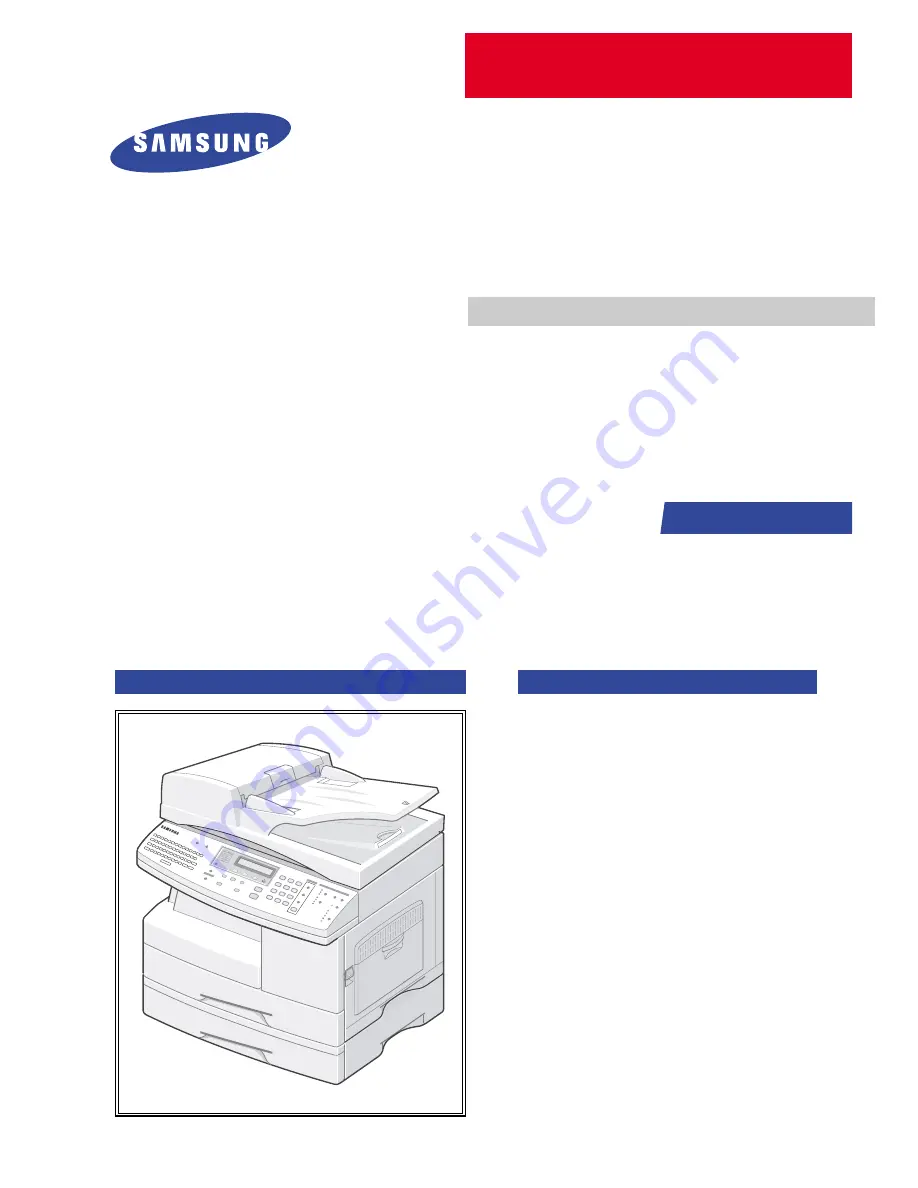
SCX-6320F/XEC
Manual
DIGITAL LASER MFP
CONTENTS
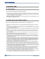
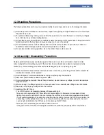
1.
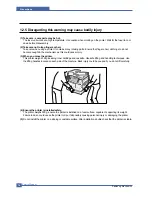
Precautions
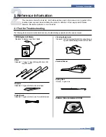
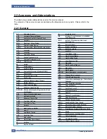
2. Reference
Information
3.
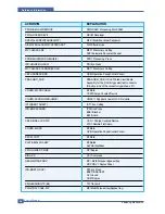
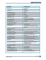
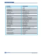
Specifications
4.
Summary of product
5. Disassembly and Reassembly
6. Alignment
and
Adjustments
7.
Troubleshooting
8.
Exploded Views and Parts List
9.
Block Diagram
10. Connection Diagram
Basic Model :
SCX-6320F
Summary of Contents for SCX-6320F
Page 7: ...Samsung Electronics Service Manual Precautions 1 6 MEMO ...
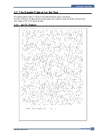
Page 15: ...Service Manual Reference Information 2 8 Samsung Electronics 2 3 2 A4 2 Pattern ...
Page 18: ...Reference Information Samsung Electronics Service Manual 2 11 MEMO ...
Page 26: ...Service Manual Summary of Product 4 4 Samsung Electronics ...
Page 27: ...Summary of Product Service Manual 4 5 Samsung Electronics ...
Page 70: ...Service Manual Precautions 5 26 Samsung Electronics MEMO ...
Page 131: ...Service Manual Troubleshooting 7 34 Samsung Electronics ...
Page 173: ...Service Manual Exploded View Parts List 8 42 Samsung Electronics MEMO ...
Page 179: ...Connection Diagrams DADF Circuit Diagram 1 4 ...
Page 180: ...Connection Diagrams DADF Circuit Diagram 2 4 ...
Page 181: ...Connection Diagrams DADF Circuit Diagram 3 4 ...
Page 182: ...Connection Diagrams DADF Circuit Diagram 4 4 ...
Page 183: ... COM ...
Page 184: ......
Page 185: ......
Page 186: ......
Page 187: ......
Page 188: ......
Page 189: ......
Page 190: ......
Page 191: ......
Page 192: ......
Page 193: ......
Page 194: ......
Page 195: ......
Page 196: ......
Page 197: ......
Page 198: ......
Page 199: ......
Page 200: ......
Page 201: ......
Page 202: ......
Page 203: ......
Page 204: ......
Page 205: ......
Page 206: ......
Page 207: ......


