background image

8_

 목차

contents

INTRODUCTION

9

9

 Features

10

 What’s 

included

11


Component names and 
functions

CONNECTION

13

13


Connecting to Monitor

13


Connecting to Power

14


Connecting to 8P Control 
Terminal

CAMERA OPERATION

16

16

 Menu 

Confi 

guration

17

 Menu 

Setup

TROUBLESHOOTING

38

38

 Troubleshooting

SPECIFICATIONS

39

39

 Specifi 

cations

41

 Dimensions

42

 Dimensions

SAMSUNG-T PROTOCOL 

COMMAND DESCRIPTION

44

44

 SAMSUNG-T 

Protocol 

Command Description

F

y

y

y

y

y

y

y

y

y

y

y

i

Summary of Contents for SCZ-3370

Page 1: ...High Resolution 37X Zoom Color Camera User Manual SCZ 3370 ...

Page 2: ...n Disclaimer Samsung Techwin makes the best to verify the integrity and correctness of the contents in this document but no formal guarantee shall be provided Use of this document and the subsequent results shall be entirely on the user s own responsibility Samsung Techwin shall have the right to change the contents of this manual without prior notice for the purpose of enhanced performance Warran...

Page 3: ...wer voltage To help you understand this manual thoroughly we ll introduce our model description SCZ 3370 SERIES NTSC MODEL PAL MODEL SCZ 3370N SCZ 3370P SCZ 3370ND SCZ 3370PD MODEL DESCRIPTION SCZ 3370X X _ _ SIGNAL SYSTEM SIGNAL SYSTEM N NTSC MODEL P PAL MODEL POWER SOURCE ...

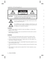
Page 4: ...se this appliance to rain or moisture To prevent injury this apparatus must be securely attached to the floor wall in accordance with the installation instructions WARNING Be sure to use only the standard adapter that is specified in the specification sheet Using any other adapter could cause fire electrical shock or damage to the product Incorrectly connecting the power supply or replacing batter...

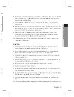
Page 5: ...t drop objects on the product or apply strong shock to it Keep away from a location subject to excessive vibrationor magnetic interference Do not install in a location subject to high temperature over 50 C low temperature below 50 C or high humidity Doing so may cause fire or electric shock If you want to relocate the already installed product be sure to turn off the power and then move or reinsta...

Page 6: ...posed of with other household waste at the end of their working life Where marked the chemical symbols Hg Cd or Pb indicate that the battery contains mercury cadmium or lead above the reference levels in EC Directive 2006 66 If batteries are not properly disposed of these substances can cause harm to human health or the environment To protect natural resources and to promote material reuse please ...

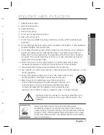
Page 7: ... the apparatus Only use attachments accessories specified by the manufacturer Use only with cart stand tripod bracket or table specified by the manufacturer or sold with the apparatus Unplug this apparatus when a card is used Use caution when moving the cart apparatus combination to avoid injury from tip over Refer all servicing to qualified service personnel Servicing is required when the apparat...

Page 8: ...tor 13 Connecting to Power 14 Connecting to 8P Control Terminal CAMERA OPERATION 16 16 Menu Configuration 17 Menu Setup TROUBLESHOOTING 38 38 Troubleshooting SPECIFICATIONS 39 39 Specifications 41 Dimensions 42 Dimensions SAMSUNG T PROTOCOL COMMAND DESCRIPTION 44 44 SAMSUNG T Protocol Command Description F y y y y y y y y y y y i ...

Page 9: ...tes in night time conditions to enhance the definition of the image INTELLIGENCE Once motion is detected the camera sends an alert signal to the processing unit which if used in conjunction with an optional alarm can provide effective surveillance of your property SSDR Samsung Super Dynamic Range For images with high contrast between bright and dark areas from difficult lighting conditions such as...

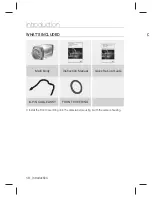
Page 10: ...oom Color Camera User Manual SCZ 3370 High Resolution 37X Zoom Color Camera Quick Set up Guide SCZ 3370 Main Body Instruction Manual Quick Set up Guide 8 PIN CABLE ASSY FRONT COVERING Ú Install the Front Cover Ring onto the camera before using it with the camera housing C ...

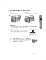
Page 11: ...se this if you want to attach the camera to the bracket Screws available for this hole should meet the following specifications Attach the bracket to the top of the camera Use screws included in the package or their equivalent less than 6mm Otherwise the bracket may not assemble to the camera properly I TOP BOTTOM 1 4 20 UNC 20 THREAD L 4 5mm 0 2mm ISO standard or 0 197 ASA standard L z wl yG pzp ...

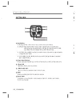
Page 12: ...se this if you want to move a menu item to a desired position or adjust the zoom factor Left F NEAR Right F NEAR Use this if you want to change the value of a selected item or adjust the focus Power Input Terminal Power supply terminal DC Type DC12V 10 DUAL Type DC12 10 AC24V 10 Power LED Illuminates when power is supplied Video Output Jack Used to connect an external video monitor in jack GND Ear...

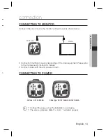
Page 13: ...ds may vary depending on the video equipment Please refer to the model specific instruction manual Connect cables with the unit powered down CONNECTING TO POWER Connect the power once the installation is complete The wire is polarized Match and terminals properly y y I CCD Camera Monitor DUAL Type DC 12V 500mA AC24V 500mA DC Type DC 12V 500mA ...

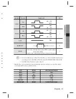
Page 14: ...ENU SEARC H MULTI REC MENU PRESE T GROU P TRACK CAM 1 2 3 4 5 6 7 8 9 0 MON CLOSE OPEN NEAR FAR WIDE TELE PTZ DVR MTX SETUP ESC FUNC ENTER 8P Control Terminal Configuration Name Cable color Description Name Cable color Description ZOOM ORANGE GND BLUE FOCUS WHITE ORANGE EX DN WHITE BLUE External D N COM GREEN 485 BROWN RS 485 communication ALARM OUT WHITE GREEN 485 WHITE BROWN RS 485 communication...

Page 15: ...must be connected to the ground I Do not simultaneously connect the RS 485 communication line when you use voltage control ZOOM and FOCUS using the RECEIVER BOX SRX 100B ALARM Output format is open collector Match the communication setup between devices when you use the wired controller SPC 200 or SPC 6000 I ITEM SPC 200 SPC 6000 Factory Default MODE Serial Serial Data Bit 8 bit 8 bit Bit Sec 9600...

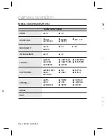
Page 16: ...OR ú INDOOR BACKLIGHT ú OFF ú BLC ú HLC ú WDR INTELLIGENCE ú OFF ú ON FOCUS ú MODE ú ZOOM TRACK ú ZOOM SPEED úD ZOOM ú ZOOM POS INIT ú USER PRESET ú LENS INIT ú RETURN EXPOSURE ú BRIGHTNESS ú IRIS ú SHUTTER ú AGC ú SSNR3 ú SENS UP ú RETURN SPECIAL ú VPS ú PRIVACY ú DAY NIGHT ú DIS ú SYNC ú COMM ADJ ú IMAGE ADJ ú DISPLAY ú RETURN RESET EXIT RN ...

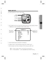
Page 17: ...s of the selected feature using the LEFT or RIGHT button 4 When completed move the arrow indicator to EXIT and press the SET button Features marked with a have an accessible submenu An item with the icon is unavailable due to function settings I MAIN SETUP 䯝 SSDR ON WHITE BAL ATW BACKLIGHT OFF INTELLIGENCE OFF FOCUS EXPOSURE SPECIAL RESET EXIT Change the status using the LEFT or RIGHT button Selec...

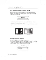
Page 18: ...y using the button so that the arrow indicates SSDR Use the button to change the SSDR level according to the contrast between bright and dark areas WHITE BAL WHITE BALANCE Use the White Balance function to adjust the screen color When the SETUP menu screen is displayed select White Bal by using the Up and Down buttons so that the arrow indicates White Bal Select a desired mode using the Up and Dow...

Page 19: ...he color temperature is between 4 500 K and 8 500 K White Balance may not work properly under the following conditions In this case select the AWC mode When the color temperature of the environment surrounding the subject is out of the control range e g clear sky or sunset When the ambient illumination of the subject is dim If the camera is directed towards a fluorescent light or is installed in a...

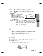
Page 20: ...P DOWN LEFT RIGHT You can adjust the position of the monitoring area HLC HIGH LIGHT COMPENSATION When a strong light such as streetlamp or headlight faces forward to the camera you can mask that exposed area in order to protect it from being saturated LEVEL You can adjust the brightness of the monitoring area LIMIT You can specify the operating conditions for enabling HLC 2 y y y WDR OFF WDR SETUP...

Page 21: ...ortion of the image If you use the VPS Virtual Progressive Scan function the CCD reads differently so you can not use WDR simultaneously If you set VPS to ON WDR will be automatically set to FIXED Mode The use of a DC lens than the manual lens is recommended to WDR optimal performance Activating BLC may cause the camera to repeat the Auto Focus operation depending on lighting conditions It is reco...

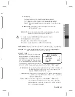
Page 22: ... POS menu DIRECTION x DIR 1 Detect an object that moves from left to right based on the specified fence line x DIR 2 Detect an object that moves from right to left based on the specified fence line x DIR 1 2 Detect an object that moves in any direction of right to left or left to right based on the specified fence line RETURN Save the fence position settings and return to the INTELLIGENCE menu 2 A...

Page 23: ...tion signal through the rear port of the camera if an object is detected to move in your specified type SMART ZOOM Smart zoom is operated in connection with MOTION DETECTION When the SMART ZOOM function is ON while the MOTION DETECTION mode is ON the zoom goes to the TARGET ZOOM position once motion is detected Once the zoom action is finished and DWELL TIME has passed the zoom returns to the STAR...

Page 24: ...of the motion detection The lower the level is the stronger the sensitivity becomes DETECT SIZE Specify the size of an object to detect on the screen The higher the level is the greater the size becomes RETURN Save the INTELLIGENCE settings and return to the SPECIAL SETUP menu y y y y y MASK AREA AREA AREA1 MODE OFF TOP IIIIÂIIIIIIIIIIIIIIIII 30 BOTTOM IIIIIIIIIIÂIIIIIIIIIII 110 LEFT ÂIIIIIIIIIIII...

Page 25: ... press SET Use the Up Down button to perform the zooming ONE PUSH After the zooming the focus will be automatically adjusted once Select the ONE PUSH mode and use the Up Down button to perform the zooming Use the Left Right button to adjust the focus MAIN SETUP SSDR ON WHITE BAL ATW BACKLIGHT OFF INTELLIGENCE OFF 䯝 FOCUS EXPOSURE FOCUS SETUP 䯝 MODE AUTO ZOOM TRACK AUTO TRACK ZOOM SPEED FAST D ZOOM...

Page 26: ... camera moves the focus track which is established OFF Only the zoom lens moves ZOOM SPEED Configure zoom tracing speed using this feature Position the indicator over ZOOM SPEED using the UP or DOWN button and then set to desired mode using the LEFT or RIGHT button D ZOOM Configure magnification limit from x2 x16 using this feature Position the indicator over D ZOOM using the UP or DOWN button Set...

Page 27: ...ratons are supported SAVE Save configured preset CLEAR Clear configured preset RETURN Revert to the FOCUS SETUP menu LENS INIT Use the left or right button in the Lens initialization item select Automatic or Manual and then press the SET button AUTO The lens can automatically be set by a pre selected day from 1 day to 7 days This will start from when the time is set Manual The Lens will reset when...

Page 28: ...cator over IRIS using the UP or DOWN button and then select the desired iris mode using the LEFT or RIGHT button AUTO The iris is automatically activated upon illumination MANUAL Manual iris configuration Set IRIS to MANUAL using the LEFT or RIGHT button and then press the SET button Increase or decrease iris level using the LEFT or RIGHT button while verifying the changes on screen y y MAIN SETUP...

Page 29: ...120 000 NTSC or from 1 50 to 1 120 000 PAL Sens Up mode can be configured manually 2x to 512x If facing the camera directly to fluorescent lighting with the shutter mode set to ESC you may encounter corrupt pixels To prevent this switch the iris mode to Auto or fix the shutter speed to 1 60 or adjust the recording position as appropriate AGC Auto Gain Control Select GAIN and use the Left Right but...

Page 30: ...s at night or under low light conditions Position the indicator over SENS UP using the UP or DOWN button Set SENS UP to the desired mode using the LEFT or RIGHT button y AUTO Select this mode for use in night time or under low light conditions y OFF Disabled If GAIN of EXPOSURE is not in use the SENS UP Sensitivity Up is set to Once AUTO mode is set the user can configure the SENS UP limit by incr...

Page 31: ...ction buttons AREA You can specify up to 12 areas to your preference MODE Determines whether to use the area selected in the AREA SEL MASK COLOR You can select one from 6 colors green red blue black white and gray that is used to fill the selected area TRANSPARENCY Specify the use of transparency on the selected area SEL POS X POS Y POS Changes the position of the selected area RETURN Saves the PR...

Page 32: ...p the switching time or speed for AUTO mode press the SET button y COLOR The picture is always displayed in color y B W The picture is always displayed in black and white DWELL TIME You can select day night switching delay time from Ą 5 7 10 15 20 30 40 60 sec DURATION You can select the day night switching point lux y EXT This mode allows you to apply a desired filter to external signals The brig...

Page 33: ...unction sets up the camera communication status when controlling the camera through an external controlled device When the SPECIAL menu screen is displayed using the UP or DOWN button so that the arrow indicates COMM ADJ Set up the mode moving the 4 direction of the SET button Protocol Select the communication PROTOCOL SAMSUNG T PELCO D PELCO P BOSCH HONEYWELL VICON AD SAMSUNG E PANASONIC CAM ID D...

Page 34: ... version of the main image The position of the collapsed image can be adjusted to your preference y H REV You can flip the picture horizontally on the screen y V REV You can flip the picture vertically on IMAGE ADJen y SHARPNESS As you increase this value the picture outline becomes stronger and clearer y Monitor Please change the settings value of video appropriate to your monitor LCD Please sele...

Page 35: ... the arrow indicator to CAM TITLE using the UP or DOWN button Set CAM TITLE to ON using the UP or DOWN button If the CAM TITLE feature is set to OFF the name will not displayed in the monitor y y I SPECIAL SETUP VPS OFF PRIVACY OFF DAY NIGHT AUTO DIS OFF SYNC INT IMAGE ADJ 䯝 DISPLAY RETURN CRT MONITOR SETUP PED LEVEL IIIIIIIIIIIÂIIIIIIIIIII 25 COLOR LEVEL IIIIIIIIIIIIIIIIIIÂIIII 5 RESET RETURN USE...

Page 36: ...select y CAM ID Displays camera ID on top left corner of the screen y CAM INFO Displays camera information on screen y ZOOM MAG Use this feature to display the current zoom magnification level on screen Position the indicator over ZOOM MAG using the UP or DOWN button Then set to ON using the LEFT or RIGHT button y FONT COLOR You can select the font color white yellow green red blue y LANGUAGE You ...

Page 37: ...English_37 CAMERA OPERATION n RESET To reset your camera to factory default condition Communication Language and Monitor settings are not initialized EXIT To finish setup menu ...

Page 38: ...ng properly and the surface of the camera is hot Check that you have properly connected the camera to an appropriate power source The SENS UP function does not work Check that AGC of EXPOSURE SETUP menu is OFF Check that SHUTTER of EXPOSURE SETUP menu is A FLK or MANUAL The Motion Detection function does not work Check if you have set the Intelligence Video Analysis mode to ON from the SPECIAL men...

Page 39: ...2x S N Y Signal 52dB AGC off Weight on Video Output CVBS 1 0 Vp p 75Ω composite Lens Type Focal Length Zoom Ratio 3 5 129 5mm Optical 37x Max Aperture Ratio 1 1 72 Wide 3 94 Tele Angular Field of View H 55 5 Wide 1 59 Tele V 42 5 Wide 1 19 Tele Min Object Distance 1 5m Focus Control Auto Manual One Push Zoom Movement Speed 2 8 sec Wide to Tele OPERATIONAL On Screen Display NTSC Multi language Supp...

Page 40: ...oax Pelco C Coaxitron RS 485 Samsung T Samsung E Pelco D Pelco P Panasonic Bosch Honeywell Vicon AD Environmental Operating Temperature Humidity 10 C 50 C 14 F 122 F Less than 90 RH Electrical Input Voltage Current Dual 24VAC 10 12VDC 10 12VDC 10 Dual 24VAC 10 12VDC 10 12VDC 10 Power Consumption Max 6 1W Max 4 7W Max 6 1W Max 4 7W Mechanical Color Material Black Silver Aluminium Dimension WxHxD 67...

Page 41: ...English_41 SPECIFICATIONS m t DIMENSIONS SCZ 3370 2 89 2 89 73 3 73 3 2 66 2 66 67 6 67 6 2 66 2 66 67 6 67 6 2 07 2 07 52 5 52 5 5 69 5 69 144 6 144 6 5 61 5 61 142 5 142 5 Unit mm Inches ...

Page 42: ...42_ specifications specifications DIMENSIONS SCZ 3370D 2 66 2 66 67 6 67 6 2 89 2 89 73 3 73 3 2 66 2 66 67 6 67 6 4 75 4 75 120 7 120 7 1 65 1 65 42 42 4 67 4 67 118 5 118 5 Unit mm Inches ...

Page 43: ...English_43 MEMO ...

Page 44: ...o far direction Command Packet A0h CAM ID HOST ADDR 0 Return Packet A0h CAM ID HOST ADDR 0 Focus Near Function Move focus lens to near direction Command Packet A0h CAM ID HOST ADDR 02 Return Packet A0h CAM ID HOST ADDR 02 Zoom Wide Function Move zoom lens to wide direction Command Packet A0h CAM ID HOST ADDR 00 Return Packet A0h CAM ID HOST ADDR 00 Zoom Tele Function Command Packet A0h CAM ID HOST...

Page 45: ...HECK SUM DDR 000Fh 00h 00h 00h 00h AFh CHECK SUM DDR 0100h 00h 00h 00h 00h AFh CHECK SUM DDR 0100h 00h 00h 00h 00h AFh CHECK SUM DDR 0200h 00h 00h 00h 00h AFh CHECK SUM DDR 0200h 00h 00h 00h 00h AFh CHECK SUM DDR 0040h 00h 00h 00h 00h AFh CHECK SUM DDR 0040h 00h 00h 00h 00h AFh CHECK SUM DDR 0020h 00h 00h 00h 00h AFh CHECK SUM DDR 0020h 00h 00h 00h 00h AFh CHECK SUM DDR 00FFh P1 P2 P3 00h AFh CHEC...

Page 46: ...SET 1 80h USER PRES ET 128 User Preset Exec Function Execute selected user preset Command Packet A0h CAM ID HOST ADDR 00 Return Packet A0h CAM ID HOST ADDR 00 Parameter P1 00h USER PRESET 1 80h USER PRES ET 128 User Preset Clear Function Clear selected user preset Command Packet A0h CAM ID HOST ADDR 00 Return Packet A0h CAM ID HOST ADDR 00 Parameter P1 00h USER PRESET 1 80h USER PRES ET 128 OSD Me...

Page 47: ...CK SUM DDR 0003h P1 00h 00h 00h Afh CHECK SUM DDR 0003h P1 00h 00h 00h Afh CHECK SUM 8 DDR 0007h P1 00h 00h 00h Afh CHECK SUM DDR 0007h P1 00h 00h 00h Afh CHECK SUM 8 DDR 0005h P1 00h 00h 00h Afh CHECK SUM DDR 0005h P1 00h 00h 00h Afh CHECK SUM 8 DDR 00B1h P1 00h 00h 00h Afh CHECK SUM DDR 00B1h P1 00h 00h 00h Afh CHECK SUM DDR 0008h 00h 00h 00h 00h AFh CHECK SUM DDR 0008h 00h 00h 00h 00h AFh CHECK...

Page 48: ...to left Command Packet A0h CAM ID HOST ADDR 00 Return Packet A0h CAM ID HOST ADDR 00 OSD Menu Right Function Move OSD arrow to right Command Packet A0h CAM ID HOST ADDR 00 Return Packet A0h CAM ID HOST ADDR 00 OSD Menu Set Function Move to inside menu Command Packet A0h CAM ID HOST ADDR 0 Return Packet A0h CAM ID HOST ADDR 0 OSD Menu ESC Function Move to upper menu Command Packet A0h CAM ID HOST A...

Page 49: ...K SUM DDR 0004h 00h 00h 00h 00h AFh CHECK SUM DDR 0004h 00h 00h 00h 00h AFh CHECK SUM DDR 0002h 00h 00h 00h 00h AFh CHECK SUM DDR 0002h 00h 00h 00h 00h AFh CHECK SUM DDR 0100h 00h 00h 00h 00h AFh CHECK SUM DDR 0100h 00h 00h 00h 00h AFh CHECK SUM DDR 0200h 00h 00h 00h 00h AFh CHECK SUM DDR 0200h 00h 00h 00h 00h AFh CHECK SUM ...

Page 50: ...MEMO ...

Page 51: ...MEMO ...

Page 52: ...MEMO ...

Page 53: ...MEMO ...

Page 54: ...MEMO ...

Page 55: ...MEMO ...

Page 56: ...3 400 TEL 82 70 7147 8740 60 FAX 82 31 8018 3745 SAMSUNG TECHWIN EUROPE LTD Samsung House 1000 Hillswood Drive Hillswood Business Park Chertsey Surrey UNITED KINGDOM KT16 OPS TEL 44 1932 45 5300 FAX 44 1932 45 5325 SAMSUNG TECHWIN AMERICA Inc 1480 Charles Willard St Carson CA 90746 UNITED STATES Toll Free 1 877 213 1222 FAX 1 310 632 2195 www samsungcctvusa com SALES NETWORK ...

Reviews: