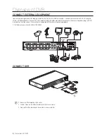
ConneCt externAl equipMent
Connect camera signal cable to video input port on the DVR via the BNC connectors. Connect your monitor to the DVR using the
VGA or HDMI video cable. Connect DVR to the power supply adapter provided. After all connections are completed, plug the DVR
in to perform function checks. Be sure that all audio/video I/O ports are connected properly.
`
The following figures are based on Model SDR-B75303.
ConneCt Dvr
M
`
Images may differ depending on the model.
`
Camera’s shape can be different depending on AIO Kit you purchased.
`
Power splitter differs depending on the number of camera connected.
Overview of DVR
8
_
Overview of DVR
2
HDMI
VGA
LAN
3
1
4
AUDIO
INPUT
AUDIO
OUTPUT
VIDEO INPUT
RS-485
12V
CAUTION
RISK O
F ELEC
TRI SHOCK
DO N
OT OPEN
CAUT
ION
: TO R
EDUCE THE RISK OF ELECTRICAL
SHOCK
DO NOT OPEN COVERS. NO USER SER
VICEABLE
PAR
TS INSI
DE. REFER SER
VICING TO QUALIFIED
SER
VICE
PERSONNEL.
WARNI
NG : TO PREVENT FI
RE OR SHOCK HAZARD. DO NOT
EXPOSE UNITS NOT S
PECIFICALL
Y DESIGNED
FOR OUTDOOR USE
TO RAIN OR MOIS
TURE.
15
16
13
14
11
12
10
9
8
7
6
5
4
3
2
1
HDMI
VGA
LAN
15
16
13
14
11
12
10
3
1
4
2
AUDIO
INPUT
AUDIO
OUTPUT
9
8
7
6
5
4
3
2
1
VIDEO INPUT
RS-485
12V
CAUTION
RISK OF ELECTRI SHOCK
DO NOT OPEN
CAUTION : TO REDUCE THE RISK OF ELECTRICAL SHOCK
DO NOT OPEN COVERS. NO USER SERVICEABLE
PARTS INSIDE. REFER SERVICING TO QUALIFIED
SERVICE PERSONNEL.
WARNING : TO PREVENT FIRE OR SHOCK HAZARD. DO NOT
EXPOSE UNITS NOT SPECIFICALLY DESIGNED
FOR OUTDOOR USE TO RAIN OR MOISTURE.
RS-485


