SENS Q40 < 4 - 3 >
4. Disassembly and Assembly
Part
Picture
Description
Main
System
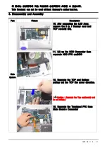
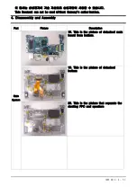
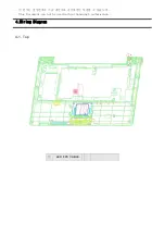
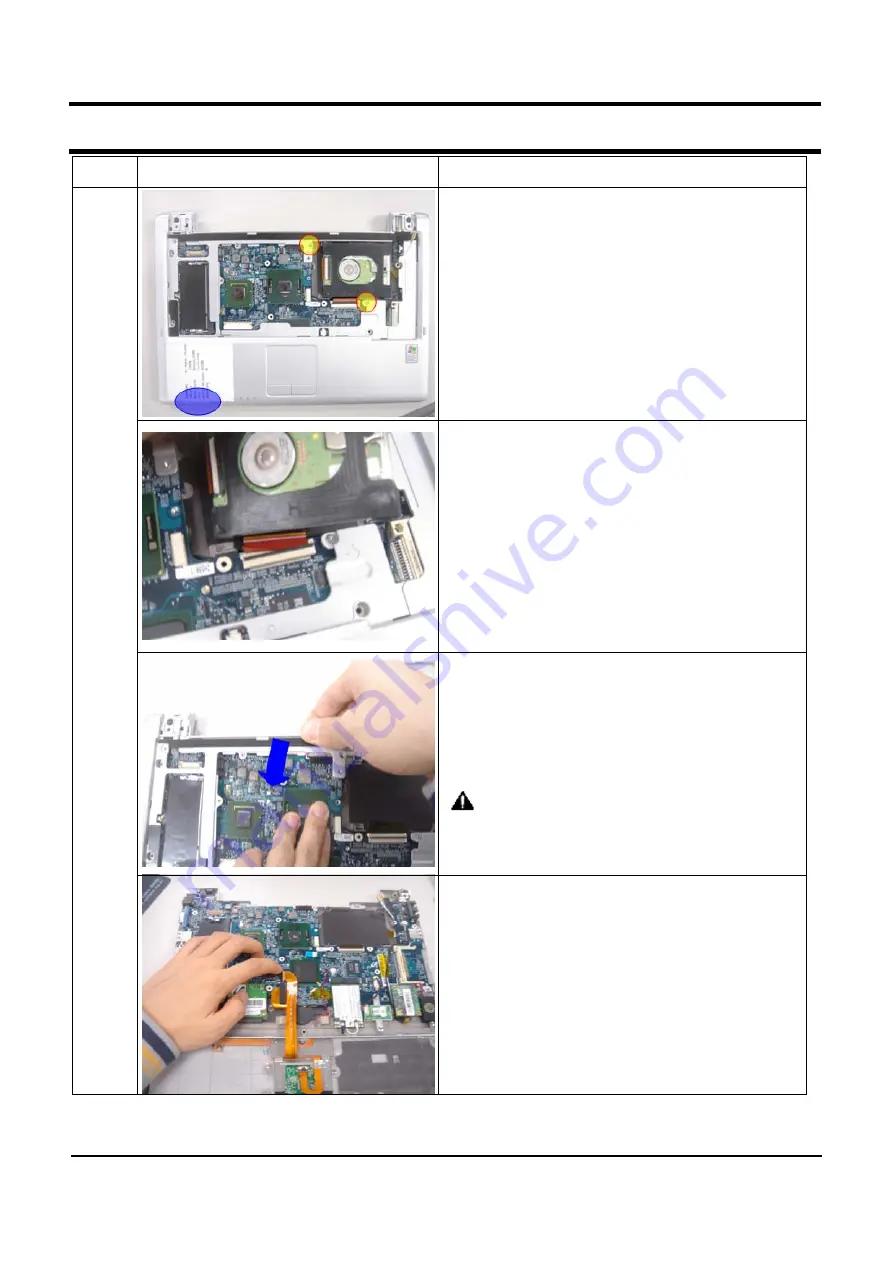
10. Afer saparating the LCD Assy,
remove the 3 in 1 Dummy card and
TOP screw(2 EA).
11. Lift up the HDD Connector then
separate HDD FPC andHDD
12. Separate the TOP and Bottom
pulling out the TOP like arrow direction.
(
Caution : Separate the Top cautioously not
to be broken.)
13. Separate the Touchpad FPC from
Main Board
’
s Connector
이 문서는 삼성전자의 기술 자산으로 승인자만이 사용할 수 있습니다.
This Document can not be used without Samsung's authorization.
11.
Summary of Contents for SENS Q40
Page 4: ...SAMSUNG Q40 1 1 1 Caution This Document can not be used without Samsung s authorization ...
Page 5: ...SENS Q40 11 1 11 References ...
Page 6: ...SENS Q40 11 2 11 References ...
Page 7: ...SENS Q40 11 3 11 References ...
Page 8: ...SENS Q40 11 4 11 References ...
Page 9: ...SENS Q40 11 5 11 References 3 ...
Page 10: ...SENS Q40 11 6 11 References ...
Page 11: ...SENS Q40 11 7 11 References ...
Page 12: ...SENS Q40 11 8 11 References ...
Page 13: ...SENS Q40 11 9 11 References ...
Page 14: ...SENS Q40 11 10 11 References ...
Page 15: ...SENS Q40 11 11 11 References ...

