background image

SENS Q40 < 4 - 4 >

4. Disassembly and Assembly

Part

Picture

Description

Main

System

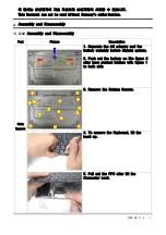
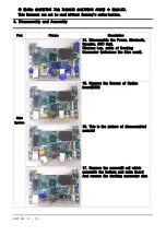
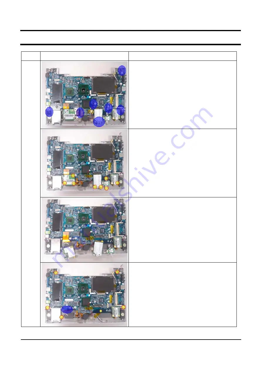
14. Disassemble the Power, Bluetooth,
Speaker, RTC Batt,
Wireless Lan, cable of Docking
Connector (reference the blue mark).

15. Remove the Screws of Option
board(8EA)

16. This is the picture of disassembled
material

17. Remove the screws(5 ea) which
assemble the bottom and main board
And remove the docking connector also

이 문서는 삼성전자의 기술 자산으로 승인자만이 사용할 수 있습니다.

This Document can not be used without Samsung's authorization.

Summary of Contents for SENS Q40

Page 1: ...Q40 FEATURES SERVICEManual SENS Q40 RIMINI NP Q40 1 High performance Note pc Intel Napa Platform with Mobile Centrino Technology High Performance Single Core 2 Comvenient Management 12 1 WXGA Super Bright Glare LCD Port Replicator X Dock support AVS SRS Sound Bluetooth 4 in 1 Multi Card Slot DMB ...

Page 2: ...lot 5 SPDIF Port 6 DMB 7 WLAN 8 Description of Main board 4 Disassembly and Assembly 1 Q40 Disassembly and Assembly 5 Troubleshooting 1 General 2 Debugging Flow Chart 3 System Diagnosis 4 H W Troubleshooting 5 Device settings Related S W Diagnosis 6 Thermal control 7 Battery Use time 6 Exploded view 1 1 LCD Back Assy 2 LCD Back Assy List 3 LCD Main 4 LCD Main List 5 Housing Top Assy 6 Housing Top ...

Page 3: ...oded view 2 1 Q40 Top 2 Q401 Bottom 3 LCD 10 Part list 1 SYSTEM 11 References 1 Safety Notice 2 Model Numbering Rule 3 Glossary 4 Hard Ware Upgrade 이 문서는 삼성전자의 기술 자산으로 승인자만이 사용할 수 있습니다 This Document can not be used without Samsung s authorization ...

Page 4: ...SAMSUNG Q40 1 1 1 Caution This Document can not be used without Samsung s authorization ...

Page 5: ...SENS Q40 11 1 11 References ...

Page 6: ...SENS Q40 11 2 11 References ...

Page 7: ...SENS Q40 11 3 11 References ...

Page 8: ...SENS Q40 11 4 11 References ...

Page 9: ...SENS Q40 11 5 11 References 3 ...

Page 10: ...SENS Q40 11 6 11 References ...

Page 11: ...SENS Q40 11 7 11 References ...

Page 12: ...SENS Q40 11 8 11 References ...

Page 13: ...SENS Q40 11 9 11 References ...

Page 14: ...SENS Q40 11 10 11 References ...

Page 15: ...SENS Q40 11 11 11 References ...

Page 16: ...ts 2 Put down top keyboard hook and lift up keyboard 3 Push the memory module tabs outward to pop the memory module upwards Carefully pull the module out at an angle of about 30 4 Push the memory module tabs outward to pop the memory module upwards Carefully pull the module out at an angle of about 30 ...

Page 17: ...eferences 2 HDD Upgrade 1 Remove the KeyBoard screw 7 points 2 Put down top keyboard hook and lift up keyboard 3 Remove the Thermal Plate Screw 4 points 4 Disassemble the HDD FPC and HDD after lifting up the HDD Connector ...

Page 18: ...SENS Q40 11 14 11 References 3 WLAN Upgrade 1 Remove theMini Card Case Screw 2 Disassemble the WLAN Cable Antenna andScrew 2 points 3 Disassemble WLAN Lifting up WLAN ...

Page 19: ... 14 1 Wide Super Bright LCD WXGA Super Bright Glare Multimedia AVS Premium Enriched 3D sound SRS WOW 4 Extensible Connective port Port replicator X Dock Option product 2 USB 4 in1 Multimedia card slot IEEE1394 VGA Bluetooth 2 0 Factory option DMB receipt function Factory option 5 Portable internet HSDPA WIBRO Ready WIBRO Using the SIM Card method Bottom side HSDPA Using the Mini Card method Top an...

Page 20: ...le Area 265 04 H x 159 824 V mm HxV LCD Resolution 1280X768 262K colors Pixel Pitch 0 2055 mm Viewing angle Hor 150 Ver 120 Contrast Ratio Typ 500 1 Brightness Typ 250 cd m2 Response time Max 50ms Graphics Controller Internal Gfx Intel 945 GMS Video Memory DVMT Max 128MB Max Resolution for LFP LVDS 1280 768 x 32Bits color WXGA Max Resolution for External Monitor 2048 x 1536 75HZ CRT Graphics Contr...

Page 21: ...n Type USB daughter card with integrated PIFA antenna Chipset Broadcom BCM2045 Standard version 2 0 DMB Module SDM 2000 Factory Option Type USB I F Antenna Int Cable Ext Rod Antenna I O Interface CF Card Slots 1 Type I Card Controller Ricoh R5C843 Support 32bit CardBus cards I O Ports iEEE1394 Port 1 6 pin USB Port 2 USB2 0 Video Port VGA port 15 pin Audio Jacks HeadPhone out Optical S PDIF MIC in...

Page 22: ...5 x 22 5mm Weight 320g Max Recharge Time 3hours Battery Life 7h Details of Cell 6cells 2Parallel 3Serial Voltage 7 4 V Battery Capacity 5200mAh Battery Rating 57 7W AC Adapter AD 6019S Output Power 60Watts Dimension 108 X 47 X 28mm Weight AC Adapter 270g typ Worldwide Compatibility Auto sensing 100 240VAC Line Frequency 50 60Hz Adapter Rating Input 100V 240V 1 8A Adapter Rating Output 19 0VDC 3 16...

Page 23: ...ini card DMB Bluetooth Lan BCM4401 10 100 BCM5751 Gigabit HDD 1 8 HDD 40 60GB 1 8 SFF HDD 40 60GB ODD External ODD 9 5 12 7mm DVD Combo DVD Super Multi Red Silver External ODD 12 7mm DVD Combo DVD Super Multi Silver Port 2 USB iEEE1394 VGA S PDIF MIC 4 in 1 SD MMC MS CF 2 USB iEEE1394 VGA S PDIF MIC 4 in 1 SD MMC MS CF DMB Option Battery 3Cell 27W 3 5hrs 6Cell 54W 7 hrs 3Cell 27W 3 5hrs 6Cell 54W ...

Page 24: ...1ABG card Intel R PRO Wireless LAN 3945ABG Network Connection devices Form registration device name Specific crops power wireless radio device for wireless data communication system 이 문서는 삼성전자의 기술 자산으로 승인자만이 사용할 수 있습니다 This Document can not be used without Samsung s authorization ...

Page 25: ...SENS Q40 2 7 이 문서는 삼성전자의 기술 자산으로 승인자만이 사용할 수 있습니다 This Document can not be used without Samsung s authorization ...

Page 26: ...00674A PATA HDD FPC CMI TOSHIBA BA41 00673A PATA HDD FPC AFC TOSHIBA BA41 00672A PATA HDD FPC AFC HITACHI MODEM BA59 01577A Foxconn T60M893 05 BA59 01578A ASKEY 1456VQL T1 INT LF MEMORY 1105 001610 512M SEC DDR2 533Mhz 512MB SO DIMM M470T6554CZ3 CD5 1105 001609 256M SEC DDR2 533Mhz 256MB SO DIMM M470T3354BG0 CD5 1105 001614 256M IN DDR2 533Mhz 256MB SO DIMM YS64T32000HDL 3 7 A 1105 001615 512M IN ...

Page 27: ...1 06GHz LCD PENEL BA59 01355A WXGA G LTD121EX1R BATTERY BA43 00138A BATTERY 3CELL Sanyo Battery 3cell BA43 00139A BATTERY 6CELL Sanyo Battery 6cell BLUETOOTH BA59 01691A BLUETOOTH BCM92045NMD 이 문서는 삼성전자의 기술 자산으로 승인자만이 사용할 수 있습니다 This Document can not be used without Samsung s authorization ...

Page 28: ...e Antenna Option BA59 01869A DMB module SDM 2000 BA42 00133A DMB Antenna KAEE BA42 00132A DMB Cable KAEE External ODD 12 7mm BA59 01624A S MULTI DV W28EA BA59 01816A S MULTI UJ 840 BA59 01687A Combo DW 224E C BA59 01565A Combo TS L462C 6 Separate sales list Docking X Dock II X Dock II 이 문서는 삼성전자의 기술 자산으로 승인자만이 사용할 수 있습니다 This Document can not be used without Samsung s authorization ...

Page 29: ...SENS X 11 3 1 3 Function of Product 1 Name of each part 1 Obverse action pilot light This Document can not be used without Samsung s authorization 3IN 1 7 Kinds ...

Page 30: ...SENS Q40 3 1 3 Function of Product This Document can not be used without Samsung s authorization HDD ODD ...

Page 31: ...SENS Q40 3 2 3 Function of Product 2 Right page 3 Left page This Document can not be used without Samsung s authorization ...

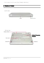
Page 32: ...SENS Q40 3 3 3 Function of Product 4 Rear page 5 Base page This Document can not be used without Samsung s authorization X Dock II Connection Connector ...

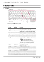
Page 33: ...SENS Q40 3 4 3 Function of Product 2 Keyboard This Document can not be used without Samsung s authorization ...

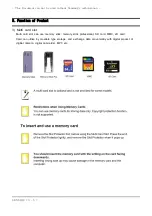
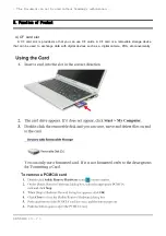
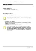
Page 34: ...t can use memory stick memory stick professional SD card MMC xD card Card can utilize by movable type storage and exchange data conveniently with digital product of digitial camera digital camcorder MP3 etc This Document can not be used without Samsung s authorization ...

Page 35: ...SENS Q40 3 6 3 Function of Product This Document can not be used without Samsung s authorization ...

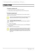
Page 36: ...F card slot is provided so that you can use CF cards A CF card is a removable storage device that can be used to exchange data with digital devices such as a digital camera PDA etc conveniently This Document can not be used without Samsung s authorization ...

Page 37: ...SENS Q40 3 8 3 Function of Product This Document can not be used without Samsung s authorization ...

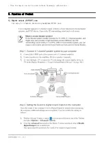
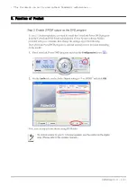
Page 38: ...SENS Q40 3 9 3 Function of Product 5 Digital output S PDIF use Can enjoy 5 1 channels sound using headphone S PDIF jack This Document can not be used without Samsung s authorization ...

Page 39: ...SENS Q40 3 10 3 Function of Product This Document can not be used without Samsung s authorization ...

Page 40: ...SENS Q40 3 11 3 Function of Product 6 To use wireless LAN This Document can not be used without Samsung s authorization ...

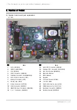
Page 41: ...oth Module 5 CardBus Controller CARDBUS500 17 MDC Module 6 LCD Cable Connector J501 18 Speaker 7 Battory Connector J529 19 CF Card Socket CF500 8 DC IN Jack J500 20 1 8 SFF HDD 9 D Sub Conector CRT500 21 RJ45 LAN Combo Jack J502 10 USB Connector USB501 22 DMB Antenna Port SIO Port 11 IEEE1394 6pin Connector IEEE500 23 Keyboard Connector KBD500 12 3 in 1 Connector SUB500 24 Sodimm Socket DDR500 Thi...

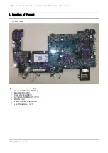
Page 42: ...Product 2 BOTTOM No Item 1 On Board Memory MEM1 2 MICOM MICOM1 3 Clockchip CLOCK1 4 SPI Flash ROM_BIOS SPI1 5 WLAN Card 6 LAN controller chip LAN1 7 Lan Transformer LT1 This Document can not be used without Samsung s authorization ...

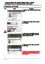
Page 43: ... Samsung s authorization Part Picture Description Main System 1 Separate the AC adapter and the battery certainly before disjoint system 2 Push out the battery on like figure 2 after have pushed latches with figure 1 to both side 3 Remove the Bottom Screws 4 To remove the Keyboard lift the hook up 5 Pull out the FPC after lift the Connector Lock ...

Page 44: ...e screws 2EA and LCD cable screw 1EA at yellow circle that combine Hinge and Top 9 Pull out the LCD cable and detach the LCD Assy Caution When separate the Antenna cable first separate antenna from Bottem by using tweezers then separate each antenna by using hand cautiously 이 문서는 삼성전자의 기술 자산으로 승인자만이 사용할 수 있습니다 This Document can not be used without Samsung s authorization ...

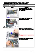
Page 45: ...ew 2 EA 11 Lift up the HDD Connector then separate HDD FPC andHDD 12 Separate the TOP and Bottom pulling out the TOP like arrow direction Caution Separate the Top cautioously not to be broken 13 Separate the Touchpad FPC from Main Board s Connector 이 문서는 삼성전자의 기술 자산으로 승인자만이 사용할 수 있습니다 This Document can not be used without Samsung s authorization 11 ...

Page 46: ...cable of Docking Connector reference the blue mark 15 Remove the Screws of Option board 8EA 16 This is the picture of disassembled material 17 Remove the screws 5 ea which assemble the bottom and main board And remove the docking connector also 이 문서는 삼성전자의 기술 자산으로 승인자만이 사용할 수 있습니다 This Document can not be used without Samsung s authorization ...

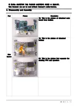
Page 47: ...System 18 This is the picture of detached main board from bottom 19 This is the picture of detached bottom 20 This is the picture that separate the docking FPC and speakers 이 문서는 삼성전자의 기술 자산으로 승인자만이 사용할 수 있습니다 This Document can not be used without Samsung s authorization ...

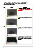
Page 48: ...rews 4EA indicated at picture 3 Lift the LCD front downward direction up slowly from the bottom end by using your hand 4 Remove the Screws 4EA which assembled LCD Hinge and screw 2EA which assembled LCD inverter board and screw 1EA which assembled LCD cable ring 이 문서는 삼성전자의 기술 자산으로 승인자만이 사용할 수 있습니다 This Document can not be used without Samsung s authorization ...

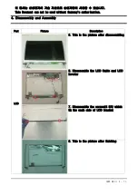
Page 49: ...he picture after disassembling 6 Disassemble the LCD Cable and LCD Invertor 7 Disassemble the screws 4 EA which fix the each side of LCD bracket 8 This is the picture after finishing 이 문서는 삼성전자의 기술 자산으로 승인자만이 사용할 수 있습니다 This Document can not be used without Samsung s authorization ...

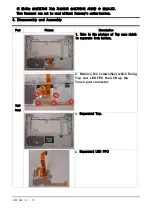
Page 50: ... is the picture of Top case which is separate from bottom 2 Remove the screws 5ea which fixing Top and LED FPC then lift up the Touch pad connector 3 Separated Top 4 Separated LED FPC 이 문서는 삼성전자의 기술 자산으로 승인자만이 사용할 수 있습니다 This Document can not be used without Samsung s authorization ...

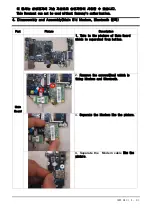
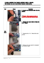
Page 51: ... This is the picture of Main Board which is separated from bottom 2 Remove the screws 2ea which is fixing Modem and Bluetooth 3 Separate the Modem like the picture 4 Separate the Modem cable like the picture 이 문서는 삼성전자의 기술 자산으로 승인자만이 사용할 수 있습니다 This Document can not be used without Samsung s authorization ...

Page 52: ...separate the cable be careful do not break down Bluetooth cable 6 Remove the screw which is fixing the 3 in 1 Board 7 Separate the 3 in 1 Board like the picture 8 Remove the tape which is attached on the RTC cable 이 문서는 삼성전자의 기술 자산으로 승인자만이 사용할 수 있습니다 This Document can not be used without Samsung s authorization ...

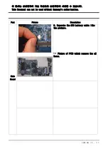
Page 53: ...cture Description Main Board 9 Separate the RTC battery cable like the picture 10 Picture of PCB which remove the all items 이 문서는 삼성전자의 기술 자산으로 승인자만이 사용할 수 있습니다 This Document can not be used without Samsung s authorization ...

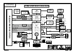
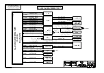
Page 54: ...RT1 R 478 uFCBGA Type Sub B D Power S W VGA USB2 0 P3 Refer to Page4 MIC WIBRO C DVI SPI P5 LAN HDD D MICOM LPC47N207 CRT A LPC IDE PCI_ EXP3 Space bar CF CARD CONN 3 3in1 B d AD1986 rev0 2 SAMSUNG PROPRIETARY AZALIA USB Left OPERATION BLOCK DIAGRAM 4 Page 35 533MHz FSB SYNAPTICS EXCEPT AS AUTHORIZED BY SAMSUNG SAMSUNG ELECTRONICS CO S PROPERTY GENERATOR DMB SIM CARD Page 24 COMBO JACK KBD MOUSE U...

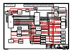
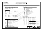
Page 55: ...1 MEM_VREF 6 1 P5V_AUX 13 1 P0 9V 14 0 KBC3_PWRON 2 1 MICOM_P3V 4 0 KBC3_LANPWRON 13 0 KBC3_PWRON 15 0 KBC3_VRON AUDIO 5 1 P3 3V_AUX 14 1 P5V 3 0 DCK3_PWRSW 18 0 CLK3_PWRGD 17 1 VCC_CORE 14 2 P1 5V 14 2 P1 5V 15 1 P2 5V 15 0 KBC3_PWRON_D 4 1 P3 3V_LAN DO NOT DISCLOSE TO OR DUPLICATE FOR OTHERS 8 3 P1 5V CLOCK 14 0 PWRON Thermal Monitor 14 2 P1 5V 19 0 VRM3_CPU_PWRGD 4 2 P3 3_LAN 14 0 PWRON 13 1 ME...

Page 56: ...NICS C 32 786KHz 25MHz 3 4 32 768KHz 133 MHz Page 6 CLK3_SMBCLK CLK0_HOST_CPU 133 MHz 33 MHz CLK1_PCIELAN CLK0_HOST_GMCH CLK1_DREFSSCLK CLK1_PCIELAN CLK1_DCKPCIELAN 133 MHz CLK1_MCH3GPLL CLK1_DCKPCIELAN CLK3_SIOPCI_DS 33 MHz CLK3_PCLKICH6M 33 MHz LPC47N207 14 318 MHz 33 MHz 33 MHz 14 318 MHz CLK3_PCLKCB 33 MHz 14 318 MHz CLK3_PCLKMICOM 33 MHz PROPRIETARY INFORMATION THAT IS CLK3_PCLKMIN 533 MHz CL...

Page 57: ...4 MICOM 26 DMB 28 USB 29 Mini PCI 30 R5C841 31 STAC9752 34 Audio AMP 35 DDR POWER 39 LED B D 44 MICOM 26 DMB 28 MDC 29 Mini PCI 30 R5C841 31 STAC9752 34 CPU VRM 40 MICOM POWER 43 LED B D 44 BLUETOOTH 28 P1 5V CPU 8 915GMS 11 ICH6 M 20 P2 5V 915GMS 11 ICH6 M 20 LCD 23 CRT 24 MICOM 26 DDR2 Termination 16 SODIMM 17 P5V_AUX Thermistor 9 ICH6 M 20 DDR POWER 39 P5V 42 P3 3V_AUX Thermal Mornitor 9 ICH6 M...

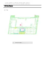
Page 58: ...4 Wiring Diagram 4 1 Top 이 문서는 삼성전자의 기술 자산으로 승인자만이 사용할 수 있습니다 This Document can not be used without Samsung s authorization LED FPC CABLE ...

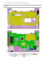
Page 59: ...4 2 Bottom 이 문서는 삼성전자의 기술 자산으로 승인자만이 사용할 수 있습니다 This Document can not be used without Samsung s authorization DMB CABLE W L SYSTEM CABLE LEFT SPEAKER CABLE RIGHT SPEAKER CABLE BLUETOOTH CABLE ...

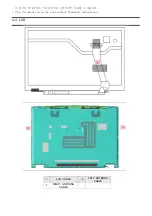
Page 60: ...4 3 LCD 이 문서는 삼성전자의 기술 자산으로 승인자만이 사용할 수 있습니다 This Document can not be used without Samsung s authorization LCD CABLE LEFT ANTENNA CABLE RIGHT ANTENNA CABLE ...

Reviews: