SENS Q40 < 4 - 6 >
4. Disassembly and Assembly
Part
Picture
Description
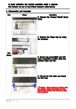
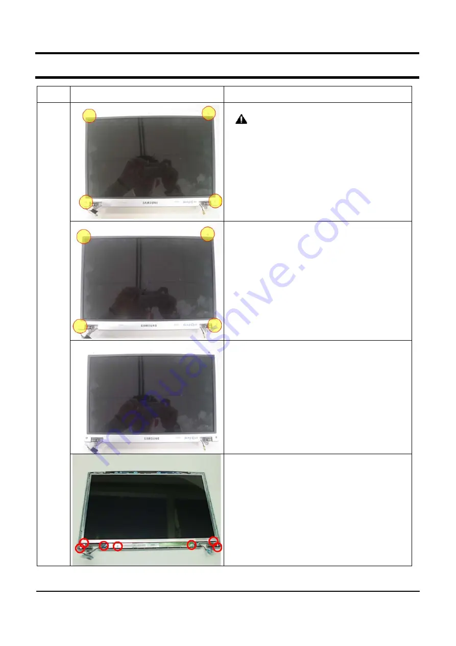
LCD
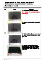
1. Removing the Rubber Foot(4EA).
(
Caution : be careful occuring the
any scratch.)
2. Remove the screws(4EA) indicated at
picture
3. Lift the LCD front(downward direction)
up slowly from the bottom end by using
your hand.
.
4. Remove the Screws(4EA) which
assembled LCD Hinge and screw(2EA)
which assembled LCD inverter board
and screw(1EA) which assembled LCD
cable ring.
이 문서는 삼성전자의 기술 자산으로 승인자만이 사용할 수 있습니다.
This Document can not be used without Samsung's authorization.
Summary of Contents for SENS Q40
Page 4: ...SAMSUNG Q40 1 1 1 Caution This Document can not be used without Samsung s authorization ...
Page 5: ...SENS Q40 11 1 11 References ...
Page 6: ...SENS Q40 11 2 11 References ...
Page 7: ...SENS Q40 11 3 11 References ...
Page 8: ...SENS Q40 11 4 11 References ...
Page 9: ...SENS Q40 11 5 11 References 3 ...
Page 10: ...SENS Q40 11 6 11 References ...
Page 11: ...SENS Q40 11 7 11 References ...
Page 12: ...SENS Q40 11 8 11 References ...
Page 13: ...SENS Q40 11 9 11 References ...
Page 14: ...SENS Q40 11 10 11 References ...
Page 15: ...SENS Q40 11 11 11 References ...

