5-2-12 Motor Controller
This facsimile machine perform sending, receving,
and printing functions utilising a single 24 volt
motor with a 120 ohm winding resistance.
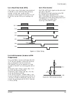
Four drive strobe pulses operate the motor.
5-2-13 Serial communication Signals
The KS16118 have two full-duplex serial
communication port.
One port is used for I-LIU communication on LIU
PBA, and is a standart UART (Universal
Asynchronous Receiver/Transmitter).
Another port, not used, may be configured for
UART or SRT (Synchronous
Receiver/Transmitter) operation.
5-2-14 Reset
To initialize the chipÕs internal logic, the reset
input (/RESET) must be held to 0 Volt for at least
22 CPU clocks. During this time, Vdd must be
greater than 3 Volt.
The watchdog timer can also invoke a system
reset.
When the reset input is released, the reset
condition continues for about 209.7 ms.
While the KS16118 is in this state, 0 Volt is applied
to the /RSTOUT pin.
[ +5V Power Monitoring ]
If 5 volt power to MX93000AFCÕs pin 6 (VPOW)
drops to between 4.6V and 4.4V (typically 4.5V),
power failure is indicated and the output of
MX93000AFCÕs pin 5 (/POWB) will go `lowÕ(GND5).
This causes the KS16118 to become active (low=reset).
The KS16118 reset causes the /REST0 terminal to be
reset.
Circuit Description
5-6
SF150T
Table 5-1: Motor Functions
Motor Function
Swing Gear Control
Document Out
100 pps
100pps
Drive Strobe Pulse
Phase
2
2
Other
100pps
2
Super Fine Mode
100pps
1-2
5-3 Memory
System memory consists of 128 kB EP-ROM and 32 kB SRAM. All of SRAM is backed up.
ROM and SRAM are selected by chip select lines, and data is accessed by the units position of the byte.
ROM has two banks. One Bank is as low bank that address range is 0100H-FFFFH.
Another bank is as high bank 10000H-1FFFFH. ROMÕs bank is selected port 0 (bit 0) of the KS16118.
5V power is applied to SRAM through VB. This model facsimile machine uses a Lithium battery.
A 1 kohm resistor in series with the positive battery terminal is for battery protection.
5-4 CODEC circuit with Modem-TX and RX signal path
This has PCB CODEC which has ablity that converts voice signal to A/D and is able to store is DRAM and convert
to voice signal passing through D/A transmission after scanning from voice digital stored in DRAM by DSP.
This has PRE-PGA(Programmable Gain Amplifier) that is able to amplift selectively among Mic input, remot
signal, rx signal.
This has ALC(Automatic Level Control) circuit has maximum 42dB gain to be convenient for recording using Mic.
This have two comparator having 1.25V reference voltage and two universal opamp.
This has 1 W speaker drive amplifir that is able to drive 8 ohm speaker.
Because MX93000AFCÕs control uses synchronous communication port, that is fast in action is convenient.


