
CIRCUIT DESCRIPTION
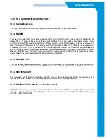
3.1.8 FAX SENDING/RECEIVING PART
3.1.8.1 General Information
The circuit is for managing the transmitting signals of Modem and between the LIU part and Modem.
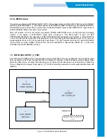
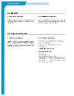
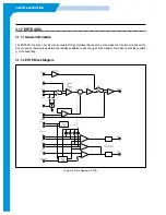
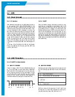
3.1.8.2 MODEM
There are two models, FM214 for the Basic model and FM 214-VS for the TAD model, which supports the Digital TAD and
Speaker Phone. The Main PCB is designed for joint use in the Rhine. The modem has the single chip fax modem function
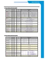
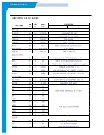
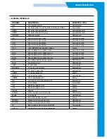
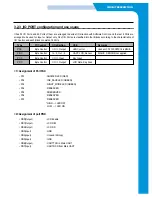
and DTMF detection/DTMF signal generation function. The principal ports of the FM214 modem are as follows when using TAD
Model. The LineOut (PIN69) is a port of the sending output from the modem, and the LineIn (PIN60) is a receiving input port.
The Modem_RST (PIN115) is the signal from the CPU for initializing modem without system power off.D0~D7 are Data Bus,
and RS0~RS4 is the signal for internal Register Selection of modem to decide mode. _MCS (PIN 91) is a signal of the Modem
Chip, and _RD (PIN 92) and _WR (PIN 90) are control signals for a reading and writing. IRQ (PIN 108) is a signal for the Modem
Interrupt Output. The transmitting speed of the FM214 is Maximum 14.4k bps.
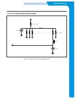
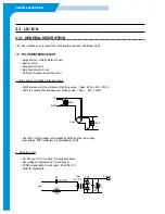
3.1.8.3 SENDING PART
The circuit manages the sending output, which is analog signal of the modem.The output signal by each mode comes out from
the modem lineout (PIN69), and it is sent out to PSTN telephone line via the Matching Transformer (600:600) of the LIU B'd.
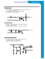
3.1.8.4 RECEIVING PART
The analog signal from the Matching Transformer (600:600) of the LIU B'd is amplified at the LIU PBA, and the second ampli-
fication is at the main input part for inputting the signal in the LINEIN (PIN60) of receiving input part.
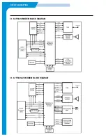
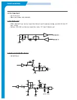
3.1.8.5 MIC INPUT PART (Not for the SF330 Basic Model)
SF335T Model has the Speaker Phone function and Tad function. For recording OGM and supporting a Speaker phone, MIC
is needed. The first amplified signal at the OPE goes to the main and makes the second amplification. After that, it is inputted
in the MIC (PIN61, 35) of modem.
Summary of Contents for SF-335T
Page 2: ......
Page 19: ...CIRCUIT DESCRIPTION 2 Chorus 2 Assigned GPO Ports for RHINE ...
Page 21: ...CIRCUIT DESCRIPTION 5 HP IMPORTANT ASIC Ports for RHINE ...
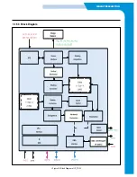
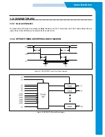
Page 24: ...CIRCUIT DESCRIPTION 3 1 5 3 Block Diagram Figure 16 Block Diagram of IP_TOP ...
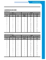
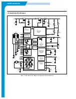
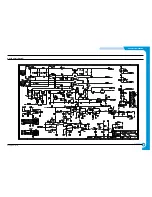
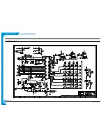
Page 35: ...CIRCUIT DESCRIPTION 3 1 8 6 FM214 MODEM BLOCK DIAGRAM 3 1 8 7 FM214 VS MODEM BLOCK DIAGRAM ...
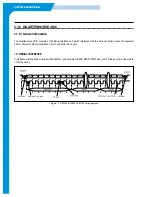
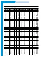
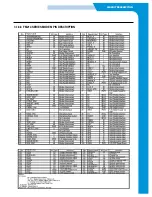
Page 36: ...CIRCUIT DESCRIPTION 3 1 8 8 FM214 SERIES MODEM PIN DESCRIPTION ...
Page 48: ...4 5 Samsung Electronics SCHEMATIC DIAGRAMS Repair Manual 4 2 LIU Circuit Diagram 2002 06 25 ...


