CIRCUIT DESCRIPTION
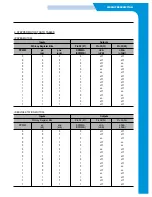
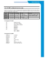
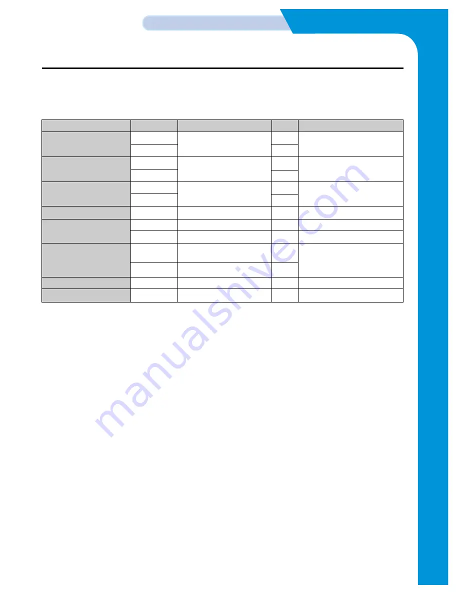
3.2.2.2 UART communication DATA
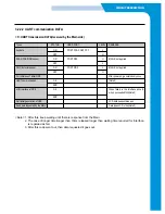
<1> UART transmission DATA(received by the Main side)
<Note> 1. After this, keep waiting until there is response from the Main.
2. The case of longer time(longer than 10ms) elapsed longer than waiting time required for Interface
is regarded as fail.
3. After this code went out, then data requested it goes out.
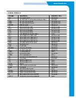
Types
STATUS
USED PORT
LEVEL
REMARKS
key data
ON
PORT PC0~PORT PC7
L
OFF
H
SCAN POSITION sensor
ON
PORT PB3
H
MAGIC not applied
OFF
L
DOC. detector sensor
ON
PORT PB-5
L
MAGIC not applied
OFF
H
For initial use of initial OPE
After power on, generated only once
UART communication
OK
(Note 2)
ERR
LCD interface of OPE
OK
When failed in the interface once &
when succeeded first(Note 2)
ERR
Self initial generation of OPE
LCD data keeps status quo
Send data requested by the Main
Data types:LCD, other(Note 3)
Summary of Contents for SF-335T
Page 2: ......
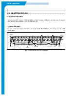
Page 19: ...CIRCUIT DESCRIPTION 2 Chorus 2 Assigned GPO Ports for RHINE ...
Page 21: ...CIRCUIT DESCRIPTION 5 HP IMPORTANT ASIC Ports for RHINE ...
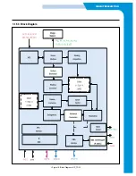
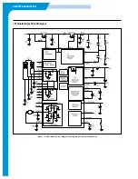
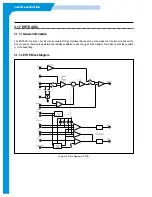
Page 24: ...CIRCUIT DESCRIPTION 3 1 5 3 Block Diagram Figure 16 Block Diagram of IP_TOP ...
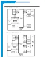
Page 35: ...CIRCUIT DESCRIPTION 3 1 8 6 FM214 MODEM BLOCK DIAGRAM 3 1 8 7 FM214 VS MODEM BLOCK DIAGRAM ...
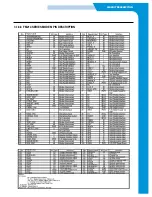
Page 36: ...CIRCUIT DESCRIPTION 3 1 8 8 FM214 SERIES MODEM PIN DESCRIPTION ...
Page 48: ...4 5 Samsung Electronics SCHEMATIC DIAGRAMS Repair Manual 4 2 LIU Circuit Diagram 2002 06 25 ...


