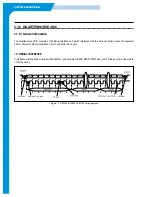
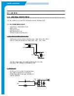
CIRCUIT DESCRIPTION
<2> Received DATA(transmitted by MAIN)
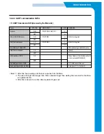
1. DATA TYPE
2. NO. OF DATA
• In case DATA is N BYTE, N+1
3. DATA
In case DATA TYPE is LCD DATA, it is configured with ASCII CODE to be displayed.
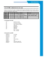
In case DATA TYPE is LED DATA, it is 1 BYTE.
• LED DATA BIT ASSIGNMENT :
4. CHECK SUM
The value done XOR all of them from DATA TYPE to DATA.
DATA BIT
BIT 0
BIT 1
BIT 2
BIT 3
BIT 4
BIT 5
BIT 6
BIT 7
LED NO.
LED 0
LED 1
LED 2
LED 3
LED 4
LED 5
LED 6
LED 7
Answer LED
Ink Save LED
Silent Mode LED
not used
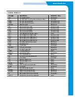
DATA types
Meaning
Remarks
a1 H
LCD DISPLAY DATA(FULL LINE)
a4 H
LED DATA
Summary of Contents for SF-335T
Page 2: ......
Page 19: ...CIRCUIT DESCRIPTION 2 Chorus 2 Assigned GPO Ports for RHINE ...
Page 21: ...CIRCUIT DESCRIPTION 5 HP IMPORTANT ASIC Ports for RHINE ...
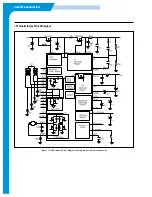
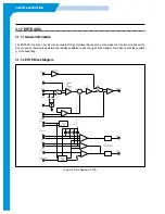
Page 24: ...CIRCUIT DESCRIPTION 3 1 5 3 Block Diagram Figure 16 Block Diagram of IP_TOP ...
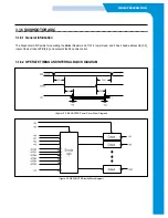
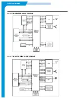
Page 35: ...CIRCUIT DESCRIPTION 3 1 8 6 FM214 MODEM BLOCK DIAGRAM 3 1 8 7 FM214 VS MODEM BLOCK DIAGRAM ...
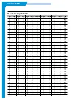
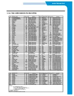
Page 36: ...CIRCUIT DESCRIPTION 3 1 8 8 FM214 SERIES MODEM PIN DESCRIPTION ...
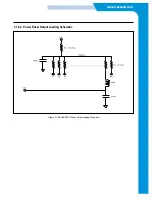
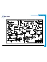
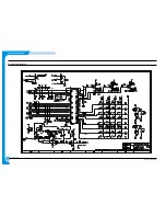
Page 48: ...4 5 Samsung Electronics SCHEMATIC DIAGRAMS Repair Manual 4 2 LIU Circuit Diagram 2002 06 25 ...


