4-11
Samsung Electronics
Disassembly and Reassembly
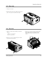
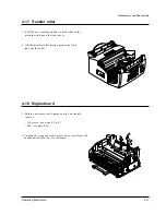
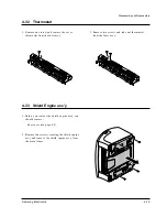
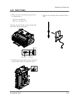
4-17 Transfer roller
1. Pull the cover release button on both sides of the
machine, and open the front cover.
2. Lift the transfer roller using a proper tool and
take out the roller.
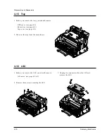
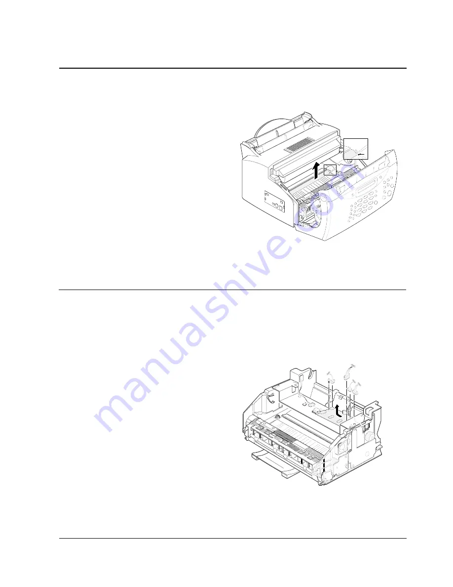
4-18 Engine board
1. Before you remove the Engine board, you should
remove:
– All covers (see page 4-3, 4-9)
– LSU (see page 4-10)
2. Unplug five connectors and remove one screw from the
engine board, then remove the board.
Summary of Contents for SF 5100
Page 10: ...2 6 Samsung Electronics Specification Memo ...
Page 16: ...3 6 Samsung Electronics Tech Mode Memo ...
Page 40: ...4 24 Samsung Electronics Disassembly and Reassembly Memo ...
Page 115: ...MEMO Samsung Electronics 8 2 ...
Page 116: ...PCB Diagrams Samsung Electronics 10 1 10 1 Main PCB Diagram Top 10 PCB Diagrams ...
Page 117: ...PCB Diagrams Samsung Electronics 10 2 10 2 Main PCB Diagram Bottom ...
Page 118: ...PCB Diagrams Samsung Electronics 10 3 10 3Engine PCB Diagram Top ...
Page 119: ...PCB Diagrams Samsung Electronics 10 4 10 4Engine PCB Diagram Bottom ...
Page 120: ...PCB Diagrams Samsung Electronics 10 5 10 5LIU PCB Diagram ...
Page 121: ...PCB Diagrams Samsung Electronics 10 6 10 6OPE PCB Diagram ...
Page 123: ...MEMO Samsung Electronics 9 2 ...
Page 184: ...MEMO Samsung Electronics 8 2 ...
Page 186: ...MEMO Samsung Electronics 9 2 ...
Page 187: ...PCB Diagrams Samsung Electronics 10 1 10 1 Main PCB Diagram Top 10 PCB Diagrams ...
Page 188: ...PCB Diagrams Samsung Electronics 10 2 10 2 Main PCB Diagram Bottom ...
Page 189: ...PCB Diagrams Samsung Electronics 10 3 10 3Engine PCB Diagram Top ...
Page 190: ...PCB Diagrams Samsung Electronics 10 4 10 4Engine PCB Diagram Bottom ...
Page 191: ...PCB Diagrams Samsung Electronics 10 5 10 5LIU PCB Diagram ...
Page 192: ...PCB Diagrams Samsung Electronics 10 6 10 6OPE PCB Diagram ...


