Samsung Electronics
4-13
Disassembly and Reassembly
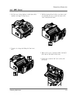
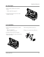
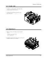
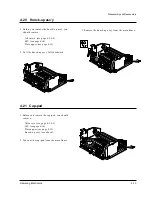
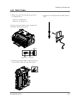
4-20 Knock-up ass’y
1. Before you remove the knock-up ass’y, you
should remove:
– All covers (see page 4-3, 4-9)
– LSU (see page 4-10)
– Plate upper (see page 4-12)
2. Pull the knock-up ass’y fully backward.
4-21 Cap-pad
1. Before you remove the cap-pad, you should
remove:
– All covers (see page 4-3, 4-5)
– LSU (see page 4-10)
– Plate upper (see page 4-12)
– Knock-up ass’y (see above)
2. Take out the cap-pad from the main frame.
3. Remove the knock-up ass’y from the main frame.
Summary of Contents for SF 5100
Page 10: ...2 6 Samsung Electronics Specification Memo ...
Page 16: ...3 6 Samsung Electronics Tech Mode Memo ...
Page 40: ...4 24 Samsung Electronics Disassembly and Reassembly Memo ...
Page 115: ...MEMO Samsung Electronics 8 2 ...
Page 116: ...PCB Diagrams Samsung Electronics 10 1 10 1 Main PCB Diagram Top 10 PCB Diagrams ...
Page 117: ...PCB Diagrams Samsung Electronics 10 2 10 2 Main PCB Diagram Bottom ...
Page 118: ...PCB Diagrams Samsung Electronics 10 3 10 3Engine PCB Diagram Top ...
Page 119: ...PCB Diagrams Samsung Electronics 10 4 10 4Engine PCB Diagram Bottom ...
Page 120: ...PCB Diagrams Samsung Electronics 10 5 10 5LIU PCB Diagram ...
Page 121: ...PCB Diagrams Samsung Electronics 10 6 10 6OPE PCB Diagram ...
Page 123: ...MEMO Samsung Electronics 9 2 ...
Page 184: ...MEMO Samsung Electronics 8 2 ...
Page 186: ...MEMO Samsung Electronics 9 2 ...
Page 187: ...PCB Diagrams Samsung Electronics 10 1 10 1 Main PCB Diagram Top 10 PCB Diagrams ...
Page 188: ...PCB Diagrams Samsung Electronics 10 2 10 2 Main PCB Diagram Bottom ...
Page 189: ...PCB Diagrams Samsung Electronics 10 3 10 3Engine PCB Diagram Top ...
Page 190: ...PCB Diagrams Samsung Electronics 10 4 10 4Engine PCB Diagram Bottom ...
Page 191: ...PCB Diagrams Samsung Electronics 10 5 10 5LIU PCB Diagram ...
Page 192: ...PCB Diagrams Samsung Electronics 10 6 10 6OPE PCB Diagram ...

