2-4
Samsung Electronics
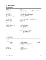
Specification
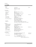
2-4 Quality
Conditions
Paper
Normal Paper
75g/m
2
Environment
Temperature : 20 ~ 25°C
Humidity : 40 ~ 60%
Print Quality
Image Density
Min. 1.3
Min. 1.0(Temperature : 10 ~ 15°C)
Background
Max. 0.2
Uniformity
Max. 0.2(Including Continuous Print)
Fusing
Min. 75% (All Black)
Start Position
Top : x ± 4.23mm, Side : y ± 4mm
From Left
Skew
Top : Max. ± 1.5mm/200mm
Side : Max. ± 2.0mm/250mm
Orthogonality
± 1.0mm
Horizontal Scan
± 0.6mm/208mm
(Bowed Line Skew : Pattern 1)
Special Paper Exception
Image Density : Min 1.0 (Envelope)
Fusing : Min. 70% (All Black)
(Envelope/OHP/Postcard)
Paper Jam
Less than 1/1,000(75g/m
2
Paper)
Paper Curl
First : Less than 16mm (10 Sheets, 75g/m
2
Paper)
After Cooling : Less than 16mm (10 Sheets, 75g/m
2
Paper)
Reliability
Insulation Resistance
Less than 10 M
Ω
(at DC 500V)
Dielectric Strength
AC 1000V (DC 1420V), 10mA
Ground Continuity
Less than 0.1
Ω
Voltage DIP
Rated Voltage ± 15%
AC Impulse Noise
AC 1000V 10, 100, 200, 400, 1000ns
Rated Power
Leakage Current
Less than 3.5mA
Surge
6 KV, 500A/3 KV, 500A
OZONE Emission
Less than 0.1 ppm (8 Hours)
Top Cover Open
Isolating the input power of the LSU,
High Voltage Part, and Fuser
Overcurrent Protect
Fuse inside the SMPS
Fusing System
Trouble Sensing
.The temperature doesn’t rise to the specific
temperature in the specific time.
.The temperature is too high.
Overheat Sensing
240 ~ 250°C (The thermostat cuts off the Fuser
from the power.)
Thermistor Open Sensing : Without the initial
temperature change of the Fuser
Indicate the
Fuser error
Summary of Contents for SF 5100
Page 10: ...2 6 Samsung Electronics Specification Memo ...
Page 16: ...3 6 Samsung Electronics Tech Mode Memo ...
Page 40: ...4 24 Samsung Electronics Disassembly and Reassembly Memo ...
Page 115: ...MEMO Samsung Electronics 8 2 ...
Page 116: ...PCB Diagrams Samsung Electronics 10 1 10 1 Main PCB Diagram Top 10 PCB Diagrams ...
Page 117: ...PCB Diagrams Samsung Electronics 10 2 10 2 Main PCB Diagram Bottom ...
Page 118: ...PCB Diagrams Samsung Electronics 10 3 10 3Engine PCB Diagram Top ...
Page 119: ...PCB Diagrams Samsung Electronics 10 4 10 4Engine PCB Diagram Bottom ...
Page 120: ...PCB Diagrams Samsung Electronics 10 5 10 5LIU PCB Diagram ...
Page 121: ...PCB Diagrams Samsung Electronics 10 6 10 6OPE PCB Diagram ...
Page 123: ...MEMO Samsung Electronics 9 2 ...
Page 184: ...MEMO Samsung Electronics 8 2 ...
Page 186: ...MEMO Samsung Electronics 9 2 ...
Page 187: ...PCB Diagrams Samsung Electronics 10 1 10 1 Main PCB Diagram Top 10 PCB Diagrams ...
Page 188: ...PCB Diagrams Samsung Electronics 10 2 10 2 Main PCB Diagram Bottom ...
Page 189: ...PCB Diagrams Samsung Electronics 10 3 10 3Engine PCB Diagram Top ...
Page 190: ...PCB Diagrams Samsung Electronics 10 4 10 4Engine PCB Diagram Bottom ...
Page 191: ...PCB Diagrams Samsung Electronics 10 5 10 5LIU PCB Diagram ...
Page 192: ...PCB Diagrams Samsung Electronics 10 6 10 6OPE PCB Diagram ...

