


3-40
CIRCUIT DESCRIPTION
Samsung Electronics
Repair Manual
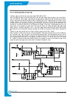
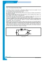
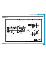
3-7-5. RING DETECTION PART
RING SIGNALS from the LINE section (TIP, RING)are further passed through C5, R3, ZD1, and ZD2 and ends up at U9, (PC
814). U9 then detects above RING SIGNAL and passes the output to MAIN B’D. The wilre diagram’s C5 is RINGER CAPAC-
ITOR and it normally uses 1UF/250V.
A R3 limits AC current and controls upper and lower REN meter.
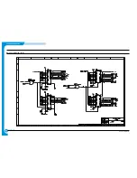
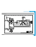
3-8 SMPS (Switching Mode Power Supply) Unit.
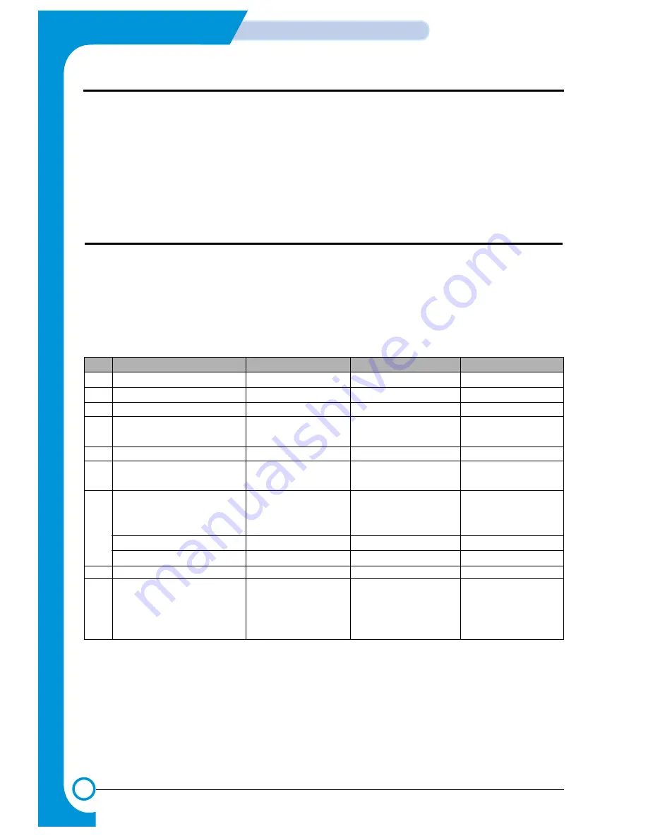
3-8-1 SMPS SPECIFICATIONS
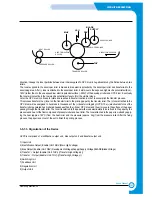
The SMPS (Switching Mode Power Supply) Unit used here is a PWM (Pulse Width Modulation) type power supply unit that
supplies DC+5V to controller and control panel, and DC+5V, DC+24V and DC+12V to the engine. It also supplies AC power
to fixer heat lamp.
No.
Output Channel
Ch.1
Ch.2
Ch.3
1
Channel Name
+5.1V
+24.0V
+12.0V
2
Rated Output Voltage
+5.1V
+24.0V
+12.0V
3
Rate Output Current
2A
2.5A
1.0A
4
Maximum Load Current
3A Continued
3.5A Continued
1.0A Continued
and Load Pattern
5
Load Change Range
0.5~2.0A
0.3~2.5A
0.2~1.0A
6
Rate output voltage
+5.1V±5%
+24.0V±10%
+12V±5%
(For rated I/O)
(+4.84~+5.35V)
(+21.60~+26.40V)
(+11.40~+12.60V)
7
1) Total Output Voltage
Including All
Including All
Including All
Deviation
+5.1V±5%
+24.0V±10%
+12V±5%
(Input, Load, Temp., Aging)
(+4.84~+5.35V)
(+21.60~+26.40V)
(+11.40~+12.60V)
2) Dynamic Input Change
Including Set Error
Including Set Error
Including Set Error
3) Dynamic Load Change
8
Refer to ripple & noise 27)
150mVp-p or less
500mVp-p or less
150mVp-p or less
9
Refer to load short and
Must not ignite or
Output voltage must
Must not ignite or
overload protection 23)
generate smoke
shutdown withing
generate smoke
Refer to load short and
when output shorted
the range of
when output shorted
overload protection 23)
for 5 sec.
3.5A~6.5A
for 5 sec.
Summary of Contents for SF-830
Page 112: ...Exploded Views and Parts List 5 34 Samsung Electronics ...
Page 116: ......
Page 163: ...4 2 SCHEMATIC DIAGRAMS Samsung Electronics Repair Manual Main Circuit Diagram 2 17 ...
Page 164: ...4 3 Samsung Electronics SCHEMATIC DIAGRAMS Repair Manual Main Circuit Diagram 3 17 ...
Page 165: ...4 4 SCHEMATIC DIAGRAMS Samsung Electronics Repair Manual Main Circuit Diagram 4 17 ...
Page 166: ...4 5 Samsung Electronics SCHEMATIC DIAGRAMS Repair Manual Main Circuit Diagram 5 17 ...
Page 167: ...4 6 SCHEMATIC DIAGRAMS Samsung Electronics Repair Manual Main Circuit Diagram 6 17 ...
Page 168: ...4 7 Samsung Electronics SCHEMATIC DIAGRAMS Repair Manual Main Circuit Diagram 7 17 ...
Page 169: ...4 8 SCHEMATIC DIAGRAMS Samsung Electronics Repair Manual Main Circuit Diagram 8 17 ...
Page 170: ...4 9 Samsung Electronics SCHEMATIC DIAGRAMS Repair Manual Main Circuit Diagram 9 17 ...
Page 171: ...4 10 SCHEMATIC DIAGRAMS Samsung Electronics Repair Manual Main Circuit Diagram 10 17 ...
Page 172: ...4 11 Samsung Electronics SCHEMATIC DIAGRAMS Repair Manual Main Circuit Diagram 11 17 ...
Page 173: ...4 12 SCHEMATIC DIAGRAMS Samsung Electronics Repair Manual Main Circuit Diagram 12 17 ...
Page 174: ...4 13 Samsung Electronics SCHEMATIC DIAGRAMS Repair Manual Main Circuit Diagram 13 17 ...
Page 175: ...4 14 SCHEMATIC DIAGRAMS Samsung Electronics Repair Manual Main Circuit Diagram 14 17 ...
Page 176: ...4 15 Samsung Electronics SCHEMATIC DIAGRAMS Repair Manual Main Circuit Diagram 15 17 ...
Page 177: ...4 16 SCHEMATIC DIAGRAMS Samsung Electronics Repair Manual Main Circuit Diagram 16 17 ...
Page 178: ...4 17 Samsung Electronics SCHEMATIC DIAGRAMS Repair Manual Main Circuit Diagram 17 17 ...
Page 180: ...4 19 Samsung Electronics SCHEMATIC DIAGRAMS Repair Manual 4 3 OPE Circuit Diagram D9 ...
Page 181: ...4 20 SCHEMATIC DIAGRAMS Samsung Electronics Repair Manual 4 4 Scan Circuit Diagram ...
Page 187: ...4 26 SCHEMATIC DIAGRAMS Samsung Electronics Repair Manual 4 8 PTL Circuit Diagram ...
Page 188: ...4 27 Samsung Electronics SCHEMATIC DIAGRAMS Repair Manual 4 10 Toner_Rx Circuit Diagram ...
Page 189: ...4 28 SCHEMATIC DIAGRAMS Samsung Electronics Repair Manual 4 11 Toner_Tx Circuit Diagram ...


