Samsung Electronics
5-5
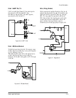
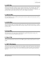
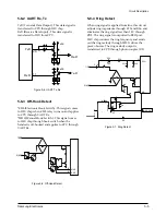
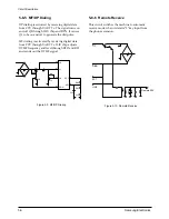
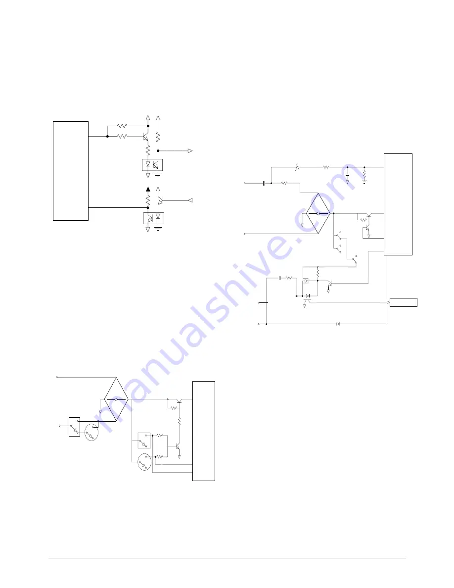
Figure 5-7 Ring Detect
5-8-4 Ring Detect
When ring signal is applied from line, this circuit
adjusts ring impedance through C19 and R26, and
eliminates the ring signal less than 18 V through
ZD2. The ring signal is outputted to RFO port.
ILIU chip counters the ring frequency and sends
out the ring melody through MO. It drives the
piezzo buzzer. The ring melody output is
transferred to CPU through photo coupler (U5).
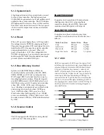
Figure 5-8 Off-Hook Detect
5-8-3 Off-Hook Detect
*EHS (Electronic Hook Switch) : This signal comes
to ILIU chip when CML relay turns on and applies
to CPU through UART Rx.
*MHS (Manual Hook Switch) : This signal comes
to ILIU chip through hook switch when the
handset is off-hooked and applies to CPU through
UART Rx.
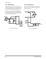
5-8-2 UART Rx, Tx
TxD (Transmit Data Output) : This data signal is
transferred to CPU through ILIU chip.
RxD (Receive Data Input) : This data signal is
transferred to ILIU from CPU.
Rx-D
vcc
vcc
Tx-D
TxD
RxD
20
11
TIP
RFO
RING
MHS
EHS
12
13
TIP
Q6
Q4
U5
28
R30
C21
R29
ZD2
18V
R26
C19
25
RFO
MO
D2
RING
RING DET
RINGER
Figure 5-6 UART Tx, Rx
Circuit Description

