background image

Samsung Electronics

8

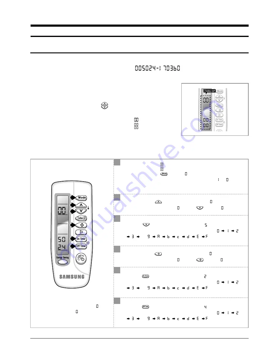
3. Set Up the Model Option

3-1 Setting Option Setup Method 

ex) Option No. :

Step 1 Enter the Option Setup mode.

1

st

Take out the batteries of remote control.

2

nd

Press the temperature 

button simultaneously and 

insert the battery again.

3

rd

Make sure the remocon display shown as         .

Step 2 Enter the Option Setup mode and select your option according to the following procedure. 

1

2

3

4

5

6

1

2

The default value is       .

Otherwise, push the          button to 

.

Every time you push the button, the display panel reads 

or 

repeatedly.

Do not touch the          button because its default is 

.

Unless the display panel reads 

, push the

button to 

.

Setting is not required if you must 

a value which has a 

default.

3

Push the          button to set the display panel to 

.

Every time you push the button, the display panel reads 

. . .

repeatedly.

4

Do not touch the

button because its default is 

.

Unless the display panel reads 

, push the

button to 

.

5

Push the

button to set the display panel to 

.

Every time you push the button, the display panel reads 

. . .

repeatedly.

6

Push the

button to set the display panel to 

.

Every time you push the button, the display panel reads 

. . .

repeatedly.

 Tsar_DB98_15869A(1)_1  1/12/04 10:04 AM  Page 8

Summary of Contents for SH05ZZ8

Page 1: ...05Z1AZD AS07Z1AZD SERVICE Manual CONTENTS AIR CONDITIONER 1 Product Specifications 2 Disassembly and Reassembly 3 Set Up the Model Option 4 Exploded Views and Parts List 5 Block Diagram 6 Schematic Di...

Page 2: ...frigerant to Change R22 g Protection Device OLP Cooling Test Condition Maximum Operation Condition SH05ZZ8 SH07ZZ8 Wall mounted 5 000 5 000 0 9 4 3 19 4 5 19 33 48 33 48 10 2 10 8 1 220 240 50 490 460...

Page 3: ...8 10 1 220 240 50 490 2 2 98 8 17 0 250V 10 16A 728x255x155 660x470x240 28 6x10 0x6 1 26 0x18 5x9 5 7 24 5 6 35 x 5 9 52 x 5 18 x 2 000 Rotary Cross flow Propeller steel steel 11 20 2ROW 10STEP 1ROW 2...

Page 4: ...ocedure Remark 1 Front Grille 1 Stop the air conditioner operation and block the main power 2 Detach tape of Grille Air Inlet 3 After Both End Part of the Grille Lower Position are pressing it shall b...

Page 5: ...to disassemble the Panel Front press in order the left center and right of the upper side of the Panel Grille with the plam of the hand to remove the hook And then disassemble the Panel Grille 1 Pull...

Page 6: ...3 Detach the Holder Pipe at the rear side 4 Loosen the 2 fixing screws of right and left side 5 Lifting the Heat Exchanger up a little to push the up side for separation from the indoor unit 1 Loosen...

Page 7: ...ng screws and detach the Cover Terminal 2 Loosen 2 fixing screws and detach the Cover Control 3 Detach the connection wire from the Terminal Block 4 Loosen 6 fixing screws and detach the Cabinet Front...

Page 8: ...tach the Motor 4 Loosen 2 fixing screws and detach the Motor Bracket from the Base 1 Loosen 2 fixing screws of left and right side 2 Disassemble the inlet and outlet pipe by welding 3 Detach the Heat...

Page 9: ...time you push the button the display panel reads or repeatedly Do not touch the button because its default is Unless the display panel reads push the button to Setting is not required if you must a v...

Page 10: ...set the display part to and check the display part The display part shows Press the Mode Selection key to set the display part to and check the display part The display part shows Step 4 Press the ON...

Page 11: ...ION ITEMS REMOCON MODEL SEG1 SEG2 SEG3 SEG4 SEG5 SEG6 SEG7 SEG8 SEG9 SEG10 SEG11 SEG12 SH05ZZ8 SH07ZZ8 0 0 5 0 2 5 1 7 0 2 1 d 0 0 5 0 2 4 1 7 0 3 6 0 SC05ZZ8 0 0 0 0 0 0 1 7 0 2 1 d AS05Z1AZD 0 0 0 0...

Page 12: ...MEMO 11 Samsung Electronics...

Page 13: ...1 4 1 5 5 1 5 4 5 2 1 3 1 2 4 2 4 5 5 5 3 3 4 3 3 3 5 3 2 3 1 9 2 1 2 2 4 1 4 3 10 1 10 2 You can search for the updated part code number through the ITSELF URL http itself sec samsung co kr 4 Explod...

Page 14: ...3 DB93 02534A ASS Y DISPLAY PCB ASS Y 1 1 1 3 4 DB63 00865A COVER DISPLAY PCB HIPS 1 1 1 3 5 DB61 01657A HOLDER LED HIPS 1 1 1 4 DB93 02513A ASS Y CONTROL IN ASS Y 1 DB93 02513B ASS Y CONTROL IN ASS Y...

Page 15: ...Samsung Electronics 14 4 2 Outdoor Unit 14 2 14 1 23 24 22 11 2 1 7 14 8 10 12 15 16 5 3 6 21 19 20 18 17 4 9 9 1 13 2 13 6 13 1 13 13 3 13 5 13 4...

Page 16: ...0109B ASS Y CABI SIDE 1 1 1 1 1 13 DB93 02608A ASS Y CONTROL OUT 1 DB93 02565A ASS Y CONTROL OUT 1 DB93 02565B ASS Y CONTROL OUT 1 DB93 02608B ASS Y CONTROL OUT 1 DB93 02608C ASS Y CONTROL OUT 1 13 1...

Page 17: ...6A DB93 02617A DB93 02508A DB61 01661A 6001 000929 6001 001054 6001 000725 DB61 00171A 3903 000095 DB32 00020A DB93 02498A DB39 00147D DB61 01656A DB93 02617B DB93 02507A DB61 01661A 6001 000929 6001...

Page 18: ...AUTO COOL DRY FAN HEAT FAN SPEED SELECT H M L BLADE H MOVING SELECT SWING STOP ENERGY SAVING ZERO VOLTAGE DETECT BLADE CONTROL INDOOR FAN MOTOR CONTROL COMPRESSOR CONTROL TEMPERATURE CONTROL TIMER BU...

Page 19: ...Samsung Electronics 18 6 Schematic Diagram 6 1 Indoor Unit This Document can not be used without Samsung s authorization...

Page 20: ...Manual is a property of Samsung Electronics Co Ltd Any unauthorized use of Manual can be punished under applicable International and or domestic law Samsung Electronics Co Ltd Jan 2004 Printed in Kor...

Reviews: