background image

Manual

WALL MOUNTED TYPE

2
0
0
4

.

2

MODEL LINE-UP

1

SPECIFICATIONS

7

OUTLINE & DIMENSION

11

PERFORMANCE DATA

17

INSTALLATION

27

FEATURES & OPERATION

45

DIAGRAM

63

TROUBLESHOOTING

75

AIR CONDITIONER

AIR CONDITIONER

2004. 2

DB98_16444A(1)_CO  2/9/04 1:47 PM  Page 1

Summary of Contents for SH07APG

Page 1: ...nual WALL MOUNTED TYPE MODEL LINE UP 1 SPECIFICATIONS 7 OUTLINE DIMENSION 11 PERFORMANCE DATA 17 INSTALLATION 27 FEATURES OPERATION 45 DIAGRAM 63 TROUBLESHOOTING 75 AIR CONDITIONER AIR CONDITIONER 2004 2 ...

Page 2: ...Model Line Up 1 1 Model Identification 1 2 Model Line Up 1 ...

Page 3: ......

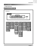
Page 4: ...MD_MR 00R 4 PD2 5 PD2_MR 6 MD2 7 MD2_MR 8 PD3 9 PD3_MR 0 Option Outdoor Sash Active A Active MR B INV C C Specification MR D Active2 E G Mold G P J Name V2 M R R T2 T Fashion F V3 C B B G G Used Q Used V Used A Sub_Set Set None Indoor I Outdoor X Set Initial Set A Indoor A Outdoor U Mode H P Q C O S Capacity Btu 30 HP Mark I A Q V 09 A 1 M E Buyer Model Name Model Code Model Identification 1 Wall ...

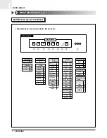
Page 5: ...utdoor unit sash PD 1 PD_MR 2 MD 3 MD_MR 4 PD2 5 PD2_MR 6 MD2 7 MD2_MR 8 PD3 9 PD3_MR 0 Active A A Specification MR B INV VSash C C Specification MR D G Mold G Active2 E Products Separated type S Capacity Btu Mode H P H C O C Tech Normal Z Tropical T INV R22 V R22 BLDC D Lower temperature model L R407C C R410A A R410A BLDC B S H 09 Z A 1 X Model Name Model Code Design of Grille type S S Standard A...

Page 6: ...2 12 3 4 34 3 8 38 1 44 5 8 58 7 8 78 1 1 8 98 Piping Division Initial F Products Export RAC S Domestic RAC R PAC P Cassette B Common Duct D Ceiling F DPM M F S 14 38 C N A Model Name Model Code Piping Parts Box Mode Export H P H C O C H P H C O C Domestic Oil G Multi M Voltage type Export None Indoor N Domestic Outdoor X Version Basic A New1 B 01R Standard Z ...

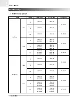
Page 7: ...GE SH12AS4 SH12AS4X AQ12S4GB UQ12S4GB FSH1412Z AQ12S4GE UQ12S4GE SC07APG SC07APGX FSC1438Z SC09APG SC09APGX SC12APG SC12APGX FSC1412Z SC07AS2 SC07AS2X AS07S2GE US07S2GE FSC1438Z SC09AS2 SC09AS2X AS09S2GB US09S2GB AS09S2GE US09S2GE SC12AS4 SC12AS4X AS12S4GB US12S4GB FSC1412Z AS12S4GE US12S4GE 7K 9K 12K 7K 9K 12K 7K 9K 12K 7K 9K 12K Mold Steel Heat Pump Cooling Only Steel Mold Indoor Unit Mode Capac...

Page 8: ...Specifications 2 1 Table 2 ...

Page 9: ......

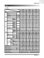
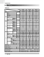
Page 10: ...x 530 x 280 35 0 x 11 2 x 7 0 27 4 x 20 9 x 11 0 8 5 34 0 ø6 35 x 7 5 ø12 7 x 7 5 ø18 x 2 000 Rotary Cross fan Propeller steel steel 15 25 2ROW 12STEP 2ROW 24STEP CAPILLARY TUBE 500 880 RBC12128 12500 Wall mounted 2 70 2 90 1 4 7 0 24 40 51 3 21 3 41 1 220 240 50 840 850 3 7 3 7 98 7 99 9 21 0 250V 10 16A 795 x 258 x 179 695 x 530 x 280 31 3 x 10 2 x 7 0 27 4 x 20 9 x 11 0 7 5 27 0 ø6 35 x 7 5 ø9 ...

Page 11: ...6A 795x258x179 660x495x235 31 3x10 2x7 0 26 0x19 5x9 3 7 5 26 0 ø6 35 x 7 5 ø9 52 x 7 5 ø18 x 2 000 Rotary Cross flow Propeller steel steel 11 20 2ROW 10STEP 1ROW 22STEP CAPILLARY TUBE 350 600 MRA99901 9201 Size Power Perfor mance Wall mounted 2 70 2 90 1 4 6 8 22 39 51 2 87 3 22 1 220 240 50 940 900 4 2 4 0 97 3 97 8 21 0 250V 10 16A 795x258x179 660x495x235 31 3x10 2x7 0 26 0x19 5x9 3 7 5 26 5 ø6...

Page 12: ...Outline Dimension 3 1 Indoor Unit 3 2 Outdoor Unit 3 ...

Page 13: ......

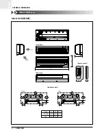
Page 14: ...ON 3 3 1 Indoor Unit PREMIUM Indoor Unit C 60 19 275 252 100 158 60 45 275 252 90 165 A B Air in Front view Rear view Remote control Type A B C 7K 9K 795 258 179 12K 890 285 179 Air out Installation plate 53 24 16 150 7K 9K 12K ...

Page 15: ...SION 3 Indoor Unit DELUXE C 60 19 275 252 100 158 60 45 275 252 90 165 A B Air in Front view Rear view Remote control Type A B C 7K 9K 795 258 179 12K 890 285 179 Air out Installation plate 22 45 115 7K 9K 12K Indoor Unit cont ...

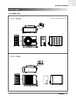
Page 16: ...SUNG 15 OUTLINE DIMENSION 3 3 2 Outdoor Unit 504 550 13 28 258 276 235 260 495 530 660 720 42 46 7K 9K 12K STEEL 7K 9K 12K MOLD Outdoor Unit 489 11 20 300 530 280 695 60 The figure in parentheses means 12K ...

Page 17: ...MEMO 16 SAMSUNG ...

Page 18: ...SAMSUNG 17 Performance Data 4 1 Performance Data 4 ...

Page 19: ...18 SAMSUNG ...

Page 20: ...ity kW Outdoor Temp DB C 35 45 Indoor Temp 4 5 3 5 2 5 1 5 DB15 0 DB20 0 DB25 0 1 0 0 0 Heating Capacity kW Outdoor Temp DB WB C 7 0 6 0 20 0 15 0 Indoor Temp Cooling Heating DB32 4 WB24 0 DB30 6 WB22 5 DB27 0 WB19 0 DB24 0 WB17 0 DB21 5 WB15 0 25 Power consumption W 35 45 Indoor Temp Outdoor Temp DB C Outdoor Temp DB WB C 1100 0 900 0 700 0 900 700 500 DB25 0 DB20 0 DB15 0 1 0 0 0 Power consumpti...

Page 21: ... Capacity kW Heating Capacity kW 35 45 1 0 0 0 7 0 6 0 20 0 15 0 Indoor Temp DB15 0 DB20 0 DB25 0 Indoor Temp Outdoor Temp DB C Outdoor Temp DB WB C Cooling Heating 1100 0 900 0 700 0 1000 800 600 Power consumption W Power consumption W 25 35 45 1 0 0 0 7 0 6 0 20 0 15 0 DB32 4 WB24 0 DB30 6 WB22 5 DB27 0 WB19 0 DB24 0 WB17 0 DB21 5 WB15 0 Indoor Temp DB25 0 DB20 0 DB15 0 Indoor Temp Outdoor Temp ...

Page 22: ... Power consumption W 35 45 1600 1400 1200 1000 1 0 0 0 Power consumption W 7 0 6 0 20 0 15 0 Indoor Temp Indoor Temp Outdoor Temp DB C Outdoor Temp DB WB C Cooling Heating 5 0 4 0 3 0 2 0 DB32 4 WB24 0 DB30 6 WB22 5 DB27 0 WB19 0 DB24 0 WB17 0 DB21 5 WB15 0 DB15 0 DB20 0 DB25 0 25 Cooling Capacity kW 35 45 5 5 4 5 3 5 2 5 1 0 0 0 Heat Capacity kW 7 0 6 0 20 0 15 0 Indoor Temp Indoor Temp Outdoor T...

Page 23: ... Capacity Correction Factors Performance Data cont Piping Length m 2590 4 2467 0 2343 7 2220 3 2097 0 1973 6 1850 3 1726 9 Input W Capacity W 7 5 15 0 847 6 831 0 814 4 797 8 781 1 764 5 747 9 731 3 714 7 698 0 7 5 15 0 Piping Length m 7 000BTU ...

Page 24: ...city Correction Factors cont Performance Data cont Input W 898 5 898 0 897 5 897 0 896 5 896 0 895 5 895 0 894 5 894 0 893 5 7 5 15 0 Piping Length m Capacity W 2650 2600 2550 2500 2450 2400 2350 2300 2250 2200 7 5 15 0 Piping Length m 9 000BTU ...

Page 25: ...3300 0 3250 0 1185 1180 1175 1170 1165 1160 1155 Input W Capacity W 7 5 15 Piping Length m 7 5 15 Refrigerant must be added if the piping length is more than 7 5metres In case of 7K and 9K models 20g of refrigerant R410A must be added for each extra metre In case of 12K model 30g of refrigerant R410A must be added for each extra metre 12 000BTU ...

Page 26: ...10 0 8 0 6 0 DB32 4 WB24 0 DB30 6 WB22 5 DB27 0 WB19 0 DB24 0 WB17 0 DB21 5 WB15 0 Low pressure kg cm G 25 35 45 Indoor Temp Outdoor Temp DB C 9 000BTU 12 000BTU 4 1 3 Low Pressure Distribution Cooling Mode Performance Data cont 12 0 10 0 8 0 6 0 DB32 4 WB24 0 DB30 6 WB22 5 DB27 0 WB19 0 DB24 0 WB17 0 DB21 5 WB15 0 25 Low pressure kg cm G 35 45 Indoor Temp Outdoor Temp DB C 7 000BTU ...

Page 27: ...MEMO 26 SAMSUNG ...

Page 28: ...allation 5 1 Selecting Area for Installation 5 2 Installation Diagram of Indoor Unit and Outdoor Unit 5 3 Performing Leak Tests 5 4 Placing the Indoor Unit in Position 5 5 Checking and Testing Operations 5 ...

Page 29: ......

Page 30: ...rea from which hot or cool air is spread evenly in a room 5 Make sure that you install the indoor unit in an area away from TVs audio units cordless phones fluorescent lighting fixtures and other electrical appliances at least 1 meter 6 Make sure that you install the indoor unit in an area which provides easy pipe connection with the outdoor unit and easy drainage for condensed water 7 Make sure t...

Page 31: ...he outdoor unit in area easy to drain condensed water from the indoor unit 7 Make sure that you install the outdoor unit in area which provides easy connection within the maximum allowable length of a coolant pipe 8 Make sure that you install the outdoor unit in an area which is large enough to accommodate the measurements shown in figure on the next page 5 1 3 Remote Control Unit 1 Make sure that...

Page 32: ...loped slightly A Indoor unit gas leak test Vinyl tape Piping Indoor unit B Drain hose installation Cut the piping hole sloped slightly Piping may be laid to the rear left right or down Wrap the refrigerant pipes and the drain hose up in the absorbent pad and the vinyl tape Triply wind the pipes and hose to the end of the indoor unit with the absorbent pad make intervals of 20mm The designs of the ...

Page 33: ... of the wooden uprights to be attached to the window frame 5 Attach the wooden upright to the window frame in a manner appropriate to the weight of the indoor unit 6 Using tapped screws attach the installation plate to the wooden upright as illustrated in the last figure opposite 5 2 2 Purging the Unit On delivery the indoor unit is loaded with an inert gas All this gas must therefore be purged be...

Page 34: ...nd of the cable through the 65mm hole in the wall 7 Replace the connector cover carefully tightening the screw 8 Close the front grille 9 For further details on how to plug the other end of the assembly cable into the outdoor unit E E N 1 1 N 1 1 N1 1 N1 N 1 1 2 3 Indoor unit Outdoor unit 1 Extend the assembly cable if necessary 2 Open the front grille by pulling on the tabs on the lower right and...

Page 35: ...irections Keep a clearance of at least 5cm between the end of the hose and the ground 5cm less Do NOT place the end of the drain hose in a hollow 1 If necessary connect the 2 meter extension to the drain hose 2 If you are using the extension insulate the inside part of the extension drain hose with a shield 3 Pass the drain hose under the refrigerant piping taking care to keep the drain hose tight...

Page 36: ... 1 Cut the pipe using a pipe cutter 2 Remove burrs at the tip of the pipe cut 3 Insert a flare nut into the pipe and modify flare 90 D A Oblique Roughness Burr Pipe Reamer Unproper flaring Inclined Surface damaged Cracked Uneven thickness CAUTION Burrs not removed may result in leakage of gas Outer diameter A mm ø6 35mm 1 3 ø9 52mm 1 8 ø12 7mm 2 0 ...

Page 37: ... packed valve having a service port as shown at the figure 4 Open the valve of the low pressure side of manifold gauge counterclockwise 5 Purge the air from the system using vacuum pump for about 10 minutes Close the valve of the low pressure side of manifold gauge clockwise Make sure that pressure gauge show 0 1MPa 76cmHg after about 10minutes This procedure is very important in order to avoid ga...

Page 38: ...e of packed valve to the open position 7 Mount the valve stem nuts and the service port cap to the valve and tighten them at the torque of 183kgf cm with a torque wrench 8 Check for gas leakage At this time especially check for gas leakage from 3 Way valve s stem nuts and from the service port cap B liquid A gas Valve stem Stem cap ...

Page 39: ...ck the pressure indicated by the pressure gauge low pressure side Standard pressure should be 4 5 5 5kg cm2 in a regular and high operation mode 6 Open the refrigerant tank and fill with refrigerant until the rated pressure is reached It is recommended not to pour the refrigerant in too quickly but gradually while operating a pres sure valve 7 Stop operation of the air conditioner 8 Close the 3 Wa...

Page 40: ...ed by a lack of refrigerant Installation position difference between the indoor unit and the outdoor unit should not exceed over than B meters When the connection pipe is been extended longer than 7 5 meters it might need to change the diameter of the electrical wire to a larger size in order to keep a voltage drop for starting room air conditioner is not less than 85 of the rated voltage And then...

Page 41: ...o close 3 Way Valve 2 Way Valve Relocation of the Air Conditioner Refer to this procedure when the unit is relocated 1 Carry out the pump down procedure refer to the details of pump down 2 Remove the power cord 3 Disconnect the assembly cable from the indoor and outdoor units 4 Remove the flare nut connecting the indoor unit and the pipe At this time cover the pipe of the indoor unit and the other...

Page 42: ...the indoor unit to the installation plate you must check that there are no gas leaks Performing Leak Tests To check for gas leaks on the Then using a leak detector check the Indoor unit Flare nuts at the end of sections C and D Outdoor unit Valves on sections A and B C D B A The designs and shape are subject to change according to the model ...

Page 43: ...insulating tape around the pipe assembly cable and drain hose 3 Place the resulting bundle carefully in the lower part of the indoor unit making sure that it does not jut out from the rear of the indoor unit 4 Hook the indoor unit up to the installation plate and move the unit to the right and left until you are sure that it is securely to place in 5 Finish wrapping insulating tape around the rest...

Page 44: ... leakages Connection wiring Heat resistant insulation of the piping Drainage Earthing wire connection Correct operations follow the steps below 2 Press the On Off button 3 Press the button 4 Air flow direction Press the button and check that the air flow blades work properly Checking and Testing Operations Result The indicator lights on the indoor unit flash at half second intervals While the indo...

Page 45: ...On Off button 3 Press the button 4 Air flow direction Press the button and check that the air flow blades work properly Result The temperature and fan settings are adjusted automatically If you press the button one or more times until or disappears the air conditioner is reset automatically to the previous mode temperature and fan settings Result The indicator lights on the indoor unit flash at ha...

Page 46: ...Features Operation 6 1 The Feature of key in Remote Control 6 2 Details for Operation Property 6 3 Operating Recommendations 6 4 Temperature and Humidity Ranges 6 ...

Page 47: ......

Page 48: ...se the temperature by the pressing the temperature button Temperature adjustment button UP To increase the temperature by the pressing the temperature button FUNCTION OF KEY Sleep button The sleep timer can be used when you are cooling or heating your room to switch the air conditioner off automatically after a period of six hours On Off button Press the button to stop or run the air conditioner F...

Page 49: ...ess the button one or more times until the required time display FUNCTION OF KEY Anion button Press the button to generate ion from the air conditioner Timer Set Cancel button After setting On Timer or Off Timer press the button to set it completely And press the button again to cancel On Timer or Off Timer set NAMED OF KEY No Off Timer button The Off Timer enables you to switch off the air condit...

Page 50: ...ing button If you wish to save energy when using your air conditioner select the Energy saving mode with the button On Off Timer Set Cancel button Press the button to stop and run the air conditioner or On Off timer set up NAMED OF KEY No Temperature adjustment button UP To increase the temperature by the pressing the temperature button Temperature adjustment button DOWN To decrease the temperatur...

Page 51: ...compulsorily can not set up the fan speed always breeze Protective function Low temperature release Prevention against freeze 5 TURBO MODE This mode is available in AUTO COOL HEAT DRY FAN MODE When this button is pressed at first the air conditioner is operated powerful state for 30 minutes regardless of the set temperature room temperature When this button is pressed again or when the operating t...

Page 52: ... 30 minutes to 24 hours 11 GENERATING ANION The air conditioner can generate anion with an ionizer in the indoor unit 12 SELF DIAGNOSIS S 07APG S 09APG S 12APG S 07AS2 S 09AS2 S 12AS4 13 BUZZER SOUND Whenever the On Off button is pressed or whenever change occurs to the condition which is set up or select the compulsory operation mode buzzer is sounded beep Indoor unit room temperature sensor erro...

Page 53: ...lects the operation mode and setting temperature 1 In case of Heat pump model 1 In case that Room Temp 21 C T the unit is operated in the Cool Mode 1 In case that Room Temp 21 C T the unit is operated in the Heat Mode 1 T means that user is able to change setting temperature within 2 C 2 In case of Cooling only model 1 In case the Room Temp 25 C T the unit is operated Compressor 1 In case the Room...

Page 54: ...xed by setting the remote controller The setting temperature will be dropped by 1 C at the starting of operation and by 1 C one hour later The operation will stop after 6 hours 6 2 5 Turbo Operation Cooling or Heating Mode If turbo operation is selected during heating or cooling mode compressor is operated for 30 minutes regardless of room temperature After 30 minutes of turbo operation the unit w...

Page 55: ...ut if you hope to control the room temperature below 26 C in the Energy saving mode the room temperature will be compelled to be 26 C If you select the Energy saving mode the up down louver will enter the Swing status OPERATION PATTERN A In the Energy saving mode when Room Temperature Tr equals to the Setting Temperature Ts or over OPERATION PATTERN B In the Energy saving mode when Room Temperatur...

Page 56: ...R may be selected in all operation status on or off If you select the AIR CLEANER function after the above operation finishes the system will enter the FAN mode AIR CLEANER function on and low fan speed 6 2 9 Anion generator control Optional If you press the ANION GENERATOR button in the remote control it will output the ANION GENERATOR Control signal The ANION GENERATOR may be selected in all ope...

Page 57: ...r heat exchanger Indoor fan speed below 28 C off 28 C below 34 C LL speed 34 C below 40 C L speed above 40 C setting speed When compressor is on 40 C 34 C 28 C 20 C Setting speed L Speed LL Speed OFF Compressor OFF OFF UL ON When compressor is off When compressor begins operating The temperature of indoor heat exchanger Indoor fan speed above 20 C UL speed below 20 C off after 10 minutes when comp...

Page 58: ...xchanger temp is over 60 C outdoor compressor stops and Indoor fan speed is low After compressor and fan are off if indoor heat exchanger temp is below 50 C indoor fan and outdoor compressor and outdoor fan operate normally Indoor Heat Exchanger Temp 60 C offset 53 C offset 50 C offset Compressor Outdoor Fan Indoor Fan ON ON Time ON OFF OFF Low Speed 3min Delay 2Sec ON Setting Speed offset 0 1 2 3...

Page 59: ... the temperature of indoor heat exchanger increase over 0 C during 6 minutes counting 6 minutes counter is cleared If the temperature of indoor heat exchanger maintains for a minute at 4 C during the 6 minutes counting switch off the compressor If the compressor is off by Low Temp Release 5 minutes release is impossible Operating Pattern Indoor Heat exchanger Temp C 5 C 0 C 1 C 6min COUNT ON COUNT...

Page 60: ...or heat exchanger is below about 40 3 C when the compressor is on it is considered as defrost B condition C condition When the accumulating time of compressor ON is over 20 minutes D condition When the accumulating time of compressor ON is over 3Hr E condition When operating time of compressor without stopping is over 6 minutes F condition If the compressor is off thermo off when the temperature o...

Page 61: ...tails for Operation Property cont Operation pattern Defrost Compressor Outdoor Fan 4Way Valve Indoor Fan ON ON ON ON 55sec 1min Defrost Time OFF OFF OFF ON ON more than 58sec 2sec 55sec 1min Low Speed Thermo ON Setting Speed OFF OFF ON ...

Page 62: ... a short time before you wish to use the room Frost When outside temperatures are low and humidity is high frost may form in the outdoor unit when heating with your air conditioner If this happens The heating operation is stopped The Deice mode is triggered automatically for about seven minutes The OPERATION indicator on the indoor unit lights up red No intervention is required from you after abou...

Page 63: ...ome other malfunction may happen if the heat exchanger freezes High humidity levels Water may condense on and drip from the surface of the indoor unit if it is used for long periods Mode Outdoor Temperature Indoor Temperature Indoor Humidity Heating 0 C to 24 C approx 27 C or less Cooling 21 C to 43 C approx 18 C to 32 C approx 80 or less Drying 18 C to 43 C approx 18 C to 32 C approx If the heati...

Page 64: ...Diagram 7 1 Refrigerating Cycle Block Diagram 7 2 Circuit Diagram 7 3 Circuit Description 7 ...

Page 65: ......

Page 66: ... 65 DIAGRAM 7 7 1 Refrigerating Cycle Block Diagram 7 1 1 HEAT PUMP PREMIUM Refrigerating Cycle Block Diagram MOLD OUTDOOR UNIT PREMIUM 7 000 9 000BTU Valve 4 Way Valve Packed 3 8 Valve Packed 1 4 Air in Capi ...

Page 67: ...66 SAMSUNG DIAGRAM 7 Refrigerating Cycle Block Diagram cont MOLD OUTDOOR UNIT Valve 4 Way Valve Packed 1 2 Valve Packed 1 4 Air in C Capi Check Valve H Capi PREMIUM 12 000BTU ...

Page 68: ...SAMSUNG 67 DIAGRAM 7 Refrigerating Cycle Block Diagram cont 7 1 2 HEAT PUMP DELUXE 12K STEEL OUTDOOR UNIT DELUXE 7 000 9 000BTU Valve 4 Way Valve Packed 3 8 Valve Packed 1 4 Air in Capi ...

Page 69: ...68 SAMSUNG DIAGRAM 7 Refrigerating Cycle Block Diagram cont STEEL OUTDOOR UNIT DELUXE 12 000BTU Valve 4 Way Valve Packed 1 2 Valve Packed 1 4 Air in Capi ...

Page 70: ...SAMSUNG 69 DIAGRAM 7 7 2 Circuit Diagram 7 2 1 S 07APG S 09APG S 12APG Indoor Unit 1 Circuit Diagram This Document can not be used without Samsung s authorization ...

Page 71: ...70 SAMSUNG DIAGRAM 7 Circuit Diagram cont S 07APG S 09APG S 12APG cont Indoor Unit 2 This Document can not be used without Samsung s authorization ...

Page 72: ...SAMSUNG 71 DIAGRAM 7 7 2 2 S 07AS2 S 09AS2 S 12AS4 Indoor Unit Circuit Diagram cont This Document can not be used without Samsung s authorization ...

Page 73: ... DIAGRAM 7 Circuit Diagram cont Outdoor Unit 7K 9K 12K This Document can not be used without Samsung s authorization Code No DB98 15123A C1 MOTOR CAPACITOR FM FAN MOTOR C2 COMP CAPACITOR O L P OVER LOAD PROTECTOR ...

Page 74: ...ecognize AC220V as 0V to determine the Switching Timing As the Fan Control Port of Micom detects the High signal and the signal turns into Low past TR Array UL2003 the LED of SSR obtains 12V the same input wave with 2 and the Gate of Photo Triac obtains the operating voltage at the same time to determine the time to turn on SSR Now the indoor fan motor can operate at the desired rpm ZERO CROSSING ...

Page 75: ...t Based on this method the signals come in the order of S1 S2 S3 and S4 to create magnetic force and one frequency forms a cycle When S1 S2 S3 and S4 receive the following signals respectively the stepping motor begins operation Power OFF Power ON S4 S2 S1 S3 M 1 1 0 0 0 2 1 1 0 0 3 0 1 0 0 4 0 1 1 0 5 0 0 1 0 6 0 0 1 1 7 0 0 0 1 8 0 0 0 1 S1 S2 S3 S4 1 0 0 0 1 2 0 0 1 1 3 0 0 1 0 4 0 1 1 0 5 0 1 ...

Page 76: ...Troubleshooting 8 1 Troubleshooting for Non Inverter 8 2 Set up the Model Option 8 ...

Page 77: ......

Page 78: ... operating although it is turned off in a HEAT mode In case of heat pump model The compressor and indoor fan stop intermittently in HEAT mode In case of heat pump model Indoor fan and outdoor fan stop operation intermittently in a HEAT mode 1 2 3 4 5 6 7 8 9 Operation of air conditioner Explanation It indicates power is on The LED stops blinking if the opera tion ON OFF button on the remote contro...

Page 79: ...ERATION TIMER TURBO Lamp flickering Lamp off No response from the remote control operation signal Unable to operate the outdoor unit Plug out and plug in 5 seconds later Press the TURBO button with the remote control In 3 minutes check the voltage between the indoor unit terminal block N 1 and 1 Able to operate the remote control Unable to operate the remote control AC198V AC242V No power source d...

Page 80: ...ower cord and plug it after 5 seconds Press the Power Button on the remote control unit to operate the air conditioner Check whether two wires of power cord are connected correctly to the terminal block and control board Check whether the fuse on the control board is normal FUSE 3 15 A 250 V Check the output of SMPS on the control board Input power AC230 15 V IC02 Input DC 12 V IC02 output DC 5 V ...

Page 81: ...from the ASS Y PCB CN43 connector and measure the sensor resistance with an ohmmeter tester Connect the sensor to CN43 supply power and measure the voltage of 1 and 2 of the CN43 connector MICOM Error or Connector CN43 check Is the sensor resistance value 10KΩ 3 at the room temperature of 25 C Yes Poor ASS Y PCB Replace Below 0 5V Yes Poor ASS Y PCB Replace Over 4 9V Indoor unit room temperature s...

Page 82: ...om pipe sensor to PCB plug in and check the voltage of connector 3 and 4 If the resistance is below 0 5V or over 4 9V replace the indoor Main PCB short or disconnected in the PCB board Temperature C 15 20 25 Temperature C 30 35 40 Resistance Value Kohm 8 31 6 94 5 83 Resistance Value Kohm 14 68 12 09 10 Others The data tolerance is 3 Room Pipe sensor failure Indoor unit heat exchanger temperature ...

Page 83: ...cted within 5 seconds Does the OPERATION lamp blink Does the Solid State Relay SS71 work properly Is the supply voltage of the fan motor sufficient Test rod location PCB CN72 Condition About AC 180V Normal voltage pin 3 and 5 Fan operating Yes Yes Yes Yes No No No Check as in the procedure NO power PCB is out of order PCB should be replaced Replace Motor Fan Capacitor Fan motor should be replaced ...

Page 84: ...r unplugging out the power cord should be reconnected within 5 seconds Does the OPERATION lamp blink Yes No Yes No No No Yes Yes Outdoor unit is out of order Power relay is out of order Power relay should be replaced PCB should be checked Micom is out of order Sensor Should be replaced Room temperature sensor is out of order Check as in the procedure No Power Is the room sensor normal resistor 10 ...

Page 85: ...when swing button of the remote control unit pushed Voltage at pin 57 60 of micom IC04 change Squarewave Voltage at pin 2 5 of CN61 motor connector change Squarewave UP DOWN louver motor is faulty Driver IC06 08 ULN2003A is faulty Micom IC04 is faulty Normal Check as in the procedure No Power After training on the heating operation should start in 5 minutes Is the number 38 of Micom IC04 DC 5 0V I...

Page 86: ...ation and check the voltage of No 3 and No 2 of the main PCB CN91 while operating the remote control When the voltage descends below 3V the assembly module PCB is normal and the main PCB is poor Then replace the main PCB 3 Replace the assembly display PCB because the module PCB is poor if the voltage between No 2 3 of CN91 maintains 5V after the remote control starts operation ...

Page 87: ...ery time you push the button the display panel reads or repeatedly Setting is not required if you must a value which has a default Push the button to set the display panel to Every time you push the button the display panel reads repeatedly 3 Push the button to set the display panel to Every time you push the button the display panel reads repeatedly 4 5 Push the button to set the display panel to...

Page 88: ...he Mode Selection key to set the display part to and check the display part The display part shows Press the Mode Selection key to set the display part to and check the display part The display part shows Step 4 Pressing the ON OFF button When pressing the operation ON OFF key with the direction of remote controller for unit the sound Ding or Diriring is heard and the OPERATION ICON lamp of the di...

Page 89: ...u push the button the display panel reads or repeatedly Push the button to set the display panel to Every time you push the button the display panel reads repeatedly Setting is not required if you must a value which has a default 3 Push the button to set the display panel to Every time you push the button the display panel reads repeatedly 4 Push the button to set the display panel to Every time y...

Page 90: ...e Selection key to set the display part to and check the display part The display part shows Press the Mode Selection key to set the display part to and check the display part The display part shows Step 4 Pressing the ON OFF button When pressing the operation ON OFF key with the direction of remote controller for unit the sound Ding or Diriring is heard and the OPERATION ICON lamp of the display ...

Page 91: ...S REMOCON MODEL SEG1 SEG2 SEG3 SEG4 SEG5 SEG6 SEG7 SEG8 SEG9 SEG10 SEG11 SEG12 SH07APG SH09APG SH12APG 0 2 6 0 6 4 1 7 0 2 2 E 0 2 6 5 6 5 1 7 0 3 5 1 0 6 7 0 6 4 1 7 0 3 6 2 SH07AS2 0 2 6 0 6 5 1 7 A 0 F b SH09AS2 0 2 6 0 6 5 1 7 A 2 2 E SH12AS4 0 6 8 0 2 4 1 7 A 3 5 1 ...

Page 92: ...MEMO SAMSUNG 91 ...

Page 93: ...MEMO 92 SAMSUNG ...

Page 94: ...ELECTRONICS Samsung Electronics Co Ltd Feb 2004 Printed in Korea Code No DB98 16444A 1 ...

Reviews: