


COLOR DOME CAMERA
User’s Manual
24
COLOR DOME CAMERA
User’s Manual
25
RETURN : Select this to save the settings for the IMAGE
ADJ. menu and to return to the SETUP menu.
• When the V-REV or H-REV mode is enabled, the text on the screen does not flip.
• If you increase the SHARPNESS level too high, the picture may become distorted or
noise may appear.
Notes
Operating Your Camera
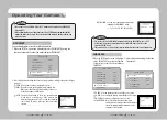
MAIN SETUP
1.LENS
DC
2.EXPOSURE
3.WHITE BAL
ATW
4.BACKLIGHT
OFF
5.SSNR
ON
6.DAY/NIGHT
AUTO
7.IMAGE ADJ
8.SPECIAL
9.EXIT
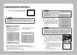
SPECIAL
1. CAM TITLE
OFF
2. SYNC
INT
3. MOTION DET
OFF
4. PRIVACY
OFF
5. DIS
OFF
6. COMM ADJ
7. LANGUAGE
ENGLISH
8. RESET
9. RETURN
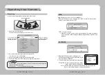
1. When the SETUP menu screen is
displayed, select ’SPECIAL‘ by using the
Function Setup switch so that the
arrow indicates ’SPECIAL‘.
2. Select a desired mode using the
Function Setup switch.
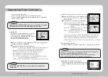
SPECIAL
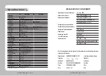
CAM TITLE : If you enter a title, the title will appear on the monitor.
… …
If the SPECIAL menu screen is displayed, use the Function Setup switch so that
the arrow indicates ’CAM TITLE‘.
…
Set it to ’ON‘ by using the Function Setup switch.
❸
Press the Function Setup switch.
❹
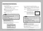
Use the Function Setup switch to move
to a desired letter and select the letter
by pressing the switch. Repeat this to
enter multiple letters. You can enter up
to 15 letters.
CAMERA TITLE SETUP
A B C D E F G H I J K L M
N O P Q R S T U V W X Y Z
a b c d e f g h i j k l m
n o p q r s t u v w x y z
- . 0 1 2 3 4 5 6 7 8 9
← →
C L R P O S E N D
• When the CAM TITLE menu is ‘OFF’, no title
will be displayed on the monitor screen
even if you enter one.
• Only English is available in this mode.
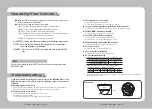
SPECIAL
1. CAM TITLE OFF
2. SYNC
INT
3. MOTION DET OFF
4. PRIVACY
OFF
Notes
…
Enter a title, move the cursor to ‘POS’ and press the
Function Setup switch. The entered title appears on
the screen. Select the position to display the title on
the screen by using the Function Setup switch and
press. When the position is determined, select ‘END’
and press the Function Setup switch to return to the
SPECIAL menu.
• If you move the cursor to CLR and press the Function Setup switch, all the letters
are deleted. To edit a letter, change the cursor to the bottom left arrow and press
the Function Setup switch. Move the cursor over the letter to be edited, move the
cursor to the letter to be inserted and then press the Function Setup switch.
Notes
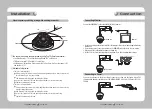
FRONT DOOR
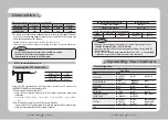
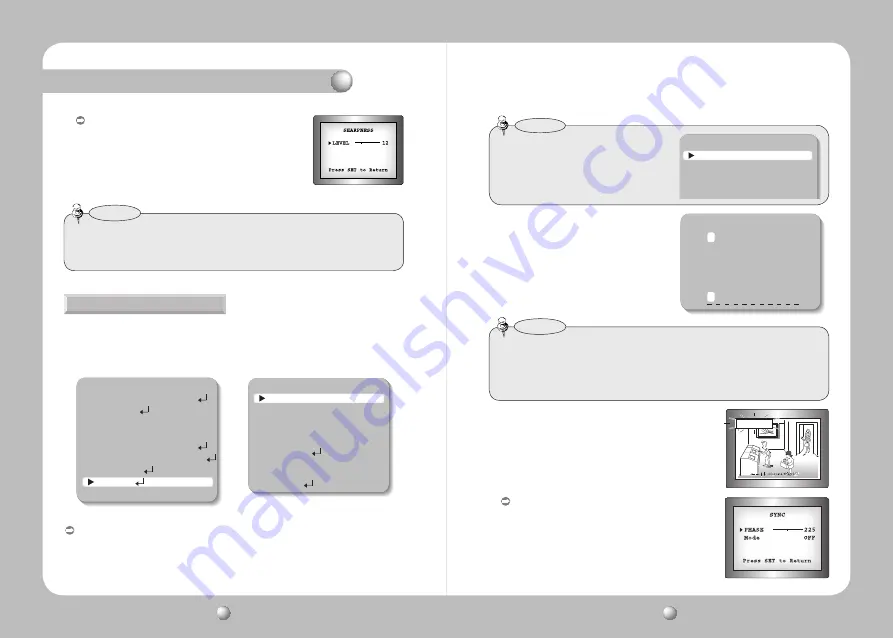
SYNC :
In areas where the supply is at 60Hz, you can
synchronize the output phase of multiple cameras
using the power synchronization function (Line-
Lock) without using a synchronization signal
generator.
- INT : Internal Synchronization Type
- L/L : Power Synchronization Type, Line-lock


