background image

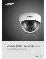
COLOR DOME CAMERA

User’s Manual

20

COLOR DOME CAMERA

User’s Manual

21

Operating Your Camera

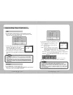
This function reduces the background noise in a low luminance environments.
1.  When the SETUP menu screen is displayed, select 'SSNR' by using the Function 

Setup switch so that the arrow indicates 'SSNR' .

SSNR

MAIN SETUP

  1.LENS SHADE 

 ON 


  2.EXPOSURE    


  3.WHITE BAL 

 ATW

  4.BACKLIGHT 

 OFF

  5.SSNR 

 ON

  6.DAY/NIGHT 

 AUTO

2. Select a desired mode using the Function Setup switch.
  Deactivates SSNR so that noise is not reduced.


OFF : Deactivates SSNR so that noise is not reduced.     


ON : Activates SSNR so that noise is reduced.    

3.  Set the SSNR mode to 'ON' and press the Function 

Setup switch. Then you can adjust the noise reduction 
level.

•  You cannot set the SSNR to 'ON' or 'OFF' when the AGC mode of the EXPOSURE 

menu is 'OFF'.

•  When adjusting the noise reduction level of the SSNR mode, remember that the 

higher the level set, the more the noise level will be reduced but that after image 
may also occur.

Notes

DAY/NIGHT

You can display pictures in color or black and white.
1.  When the SETUP menu screen is displayed, select‘DAY/NIGHT’by using the Up and 

Down buttons so that the arrow indicates‘DAY/NIGHT’.

MAIN SETUP

  1.LENS SHADE 

  DC    

  2.EXPOSURE   
  3.WHITE BAL 

  ATW

  4.BACKLIGHT 

  OFF

  5.SSNR 

  ON  

  6.DAY/NIGHT 

  AUTO   

  7.IMAGE ADJ  

2.  Select a desired mode using the Left and Right buttons according to the picture display you want.

 COLOR :  The picture is always displayed in color (IR 

LED : OFF)

  B/W :  The picture is always displayed in black and 

white (IR LED : ON)

 AUTO :  The mode is switched to ’Color‘ in a normal 

environment, but switches to B/W mode(IR LED 
: ON) when ambient illumination is low. To set 
up the switching time or speed for AUTO mode, press the SET button.

    - DWELL TIME :  You can select the duration time about changing the day/night mode. 

3s, 5s, 7s, 10s, 15s, 20s, 30s, 40s, 60s

    - DURATION :  You can select the brightness level at which the camera switches from day to 

night mode.

*  Light levels are often site dependant.

Color 

→…

B/W

B/W 

→…

Color

Fast

2.5 lux

5 lux

Slow

1lux

10 lux

•  You cannot control the DAY/NIGHT menu when AGC in the EXPOSURE menu is ‘OFF’. 

At this time, the exchange between DAY mode and NIGHT mode operates as like selecting 

‘COLOR’ mode.

•  The OSD key does not work for 3 seconds when switching to Color or B/W, to ensure 

stable camera operation.

Notes

 EXTERN : This mode allows you to apply a desired filter to external signals.

Summary of Contents for SIR-60

Page 1: ... IR Dome Camera SIR 60 User sManual Thank you for purchasing a SAMSUNG Dome CAMERA Before attempting to connect or operate this product please read these instructions carefully and save this manual for future use ENGLISH ...

Page 2: ...operated in a commercial environment This equipment generates uses and can radiate radio frequency energy and if not installed and used in accordance with the instruction manual may cause harmful interference to radio communications Operation of this equipment in a residential area is likely to cause harmful interference in which case the user will be required to correct the interference at his ow...

Page 3: ...tal Image Stabilizer The DIS function compensates for any camera movement to produce more stable pictures Indoor Visibility range 7M In B W mode the IR LEDs are illuminated the indoor visibility range at 0Lux is 7m IR MODE Function Miscellaneous Functions The intensity of the IR LEDs automatically adjust depending upon the closeness of the object to prevent saturation HLC High Light Compensation S...

Page 4: ...we can t compensate for material loss and or personalinjuriesbyrobbery fire naturaldisasterorsomethinglikethistype Ignoring this information may result in material loss and or serious personal injuries including death Indicates Never Allowed Ignoring this information may result in material loss and or a slight injuries Indicates No Disassembling Warnings Cautions Warning Attention Special Mark Mes...

Page 5: ... abrasive or opaque substances on the dome cover SIR 60 2Instruction Manual 3M4 Tapping Screw 3EA If it is exposed to radioactivity For heated CCD it will be out of order May reduce the performance of the camera Components and Accessories Pan Base control panning angle of camera 2 Tilt Base control tilting angle of camera 3 Lens Module f 3 6mm F2 0 IR Lens 4 Power Input Connector 5 Video Output Ja...

Page 6: ...ld the ceiling bracket located where the arrow points to and separate it from the main body of the camera by rotating it counterclockwise refer to the picture in Notes on page 10 2 Adjust the camera lens to face the area to be monitored and fix the main body and the dome cover by aligning the grooves and rotating the body clockwise Installation Latch Figure 1 Locking Direction Clockwise Main Body ...

Page 7: ...ing angle by rotating the tilt base 3Tighten pan and tilt securing screw Adjust the panning and tilting while watching the monitor Installation Connect theVIDEO OUT jack to theVIDEO IN jack of monitor As the connecting method varies with the instruments refer to the manual supplied with the instrument Only connect the cable when the power is turned off Set the 75Ω Hi Z selection switch as shown be...

Page 8: ...ITE BALANCE ATW MANUAL AWC SET OUTDOOR INDOOR BACKLIGHT BLC HLC OFF SSNR ON OFF DAY NIGHT COLOR B W AUTO IMAGE ADJUSTMENT IMAGEADJ V REV H REV D ZOOM SHARPNESS RETURN SPECIAL CAMTITLE SYNC MOTION DET PRIVACY DIS LANGUAGE IR MODE RESET RETURN EXIT Connection Use the Function Setup switch beside of the lens 1 Press the Function Setup switch Main setup menu is displayed on the monitor screen 2 Select...

Page 9: ...rom 5 3dB to 32dB HIGH Allows automatic gain control from 5 3dB to 37dB SENS UP When it is night or dark the camera automatically detects the light level and maintains a clear picture if this mode is activated OFF Deactivates the SENS UP function AUTO Activates the SENS UP function RETURN Select this to save the changes in the EXPOSURE menu and return to the SETUP menu If you press the Function Se...

Page 10: ...urpose BLC Enables a user to directly select a desired area from a picture and to view the area more clearly HLC High Light Compensation If there is a high light installed in a limited environment such as an apartment parking garage or gas station entrance removing the high light makes it possible to view car license plates efficiently DAY In normal daylight conditions the HLC is not activated NIG...

Page 11: ...t DAY NIGHT by using the Up and Down buttons so that the arrow indicates DAY NIGHT MAIN SETUP 1 LENS SHADE DC 2 EXPOSURE 3 WHITE BAL ATW 4 BACKLIGHT OFF 5 SSNR ON 6 DAY NIGHT AUTO 7 IMAGE ADJ 2 Select a desired mode using the Left and Right buttons according to the picture display you want COLOR The picture is always displayed in color IR LED OFF B W The picture is always displayed in black and wh...

Page 12: ...st this value appropriately depending on the sharpness of the picture RETURN Select this to save the settings for the IMAGE ADJ menu and to return to the SETUP menu When theV REV or H REV mode is enabled the text on the screen does not flip If you increase the SHARPNESS level too high the picture may become distorted or noise may appear Notes IMAGE SETUP 1 V REV OFF 2 H REV OFF 3 D ZOOM OFF 4 SHAR...

Page 13: ... synchronize the output phase of multiple cameras using the power synchronization function Line Lock without using a synchronization signal generator INT InternalSynchronizationType L L PowerSynchronizationType Line lock FRONT DOOR CAMERA TITLE SETUP A B C D E F G H I J K L M N O P Q R S T U V W X Y Z a b c d e f g h i j k l m n o p q r s t u v w x y z 0 1 2 3 4 5 6 7 8 9 C L R P O S E N D CAMTITL...

Page 14: ...can select up to 8 PRIVACY areas AREA MODE Determines whether to use the area selected in the AREA SEL and the size and position of the area MASK COLOR Determine area color You can select Gray Black andWhite TRANSP Determine the transparency of selected area as controlling number from 0 to 3 RETURN Select this to save the PRIVACY menu settings and return to the SPECIAL menu PRIVACY Mask an area yo...

Page 15: ...T function setting up the color mode Please change theAUTO or B W mode Troubleshooting Specifications SIR 60N SIR 60P ELECTRICAL InputVoltage DC 12V Power Consumption Max 2 5W VIDEO Imaging Device 1 3 inch Diagonal 6mm Super HAD CCD Total Pixels 811 H x 508 V 795 H x 596 V Effective Pixels 768 H x 494 V 752 H x 582 V Scanning System 2 1 Interlace Synchronization Internal Frequency H 15 734KHz V 59...

Page 16: ...uipment Type Environment CCTV Camera Model Name SIR 60P Beginning Serial NO C11S3010007 Year of Manufacture 2009 03 01 Conformance to EN 50081 1 1992 EMC Directive 89 336 EEC and 92 31 EEC EN 50130 4 1996 We the undersigned hereby declare that the equipment specified above conforms to the above Directive s Manufacturer SAMSUNGTECHWIN CO LTD LegalRepresentativeinEurope Signature Signature Full Name...

Page 17: ...TEL 82 31 740 8151 8 FAX 82 31 740 8145 SAMSUNG TECHWIN EUROPE CO LTD Samsung House 1000 Hillswood Drive Hillswood Business Park Chertsey Surrey UNITED KINGDOM KT16 OPS TEL 44 1932 45 5300 FAX 44 1932 45 5325 SAMSUNG TECHWIN AMERICA Inc 1480 Charles Willard St Carson CA 90746 UNITED STATES Tol Free 1 877 213 1222 FAX 1 310 632 2195 www samsungcctvusa com SALES NETWORK ...

Reviews: