Alignment and Adjustments
3-6
Samsung Electronics
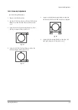
3-4-5 CATHODE VOLTAGE ADJUSTMENT
(SCREEN ADJUSTMENT)
1. Enter to G2-Adjust mode in Factory mode.
2. Disconnect all input signal.
3. Adjust the Screen VR (on the FBT) so that the OSD on the monitor bewnes “SCREEN : OK”.
3-4-6 PURITY ADJUSTMENT
1. Warm up the receiver for at least 20 minutes.
2. Plug in the CRT deflection yoke and tighten the clamp screw.
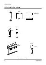
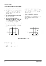
3. Plug the convergence yoke into the CRT and set in as shown in Fig. 4-1
4. Input a black and white signal.
5. Fully demagnetize the receiver by applying an external degaussing coil.
6. Turn the CONTRAST and BRIGHTNESS controls to maximum.
7. Loosen the clamp screw holding the yoke. Slide the yoke backward or forward to provide vertical green
belt. (Fig. 4-2).
8. Tighten the convergence yoke.
9. Slowly move the deflection yoke forward, and adjust for the best overall green screen.
10. Temporarily tighten the deflection yoke.
11. Produce blue and red rasters by adjusting the low-light controls. Check for good purity in each field.
12. Tighten the deflection yoke.
4 Pole Magnet
6 Pole Magnet
2 Pole Magnet
Clamper
Screw
Fig. 4-1 Convergence Magnet Assembly
Summary of Contents for SM0-150TPV
Page 17: ...3 10 Samsung Electronics MEMO ...
Page 37: ...8 PCB Diagrams Samsung Electronics PCB Diagrams 8 1 8 1 PATTERN ...
Page 38: ...8 2 TOP PCB Diagrams 8 2 Samsung Electronics ...
Page 40: ...9 2 Samsung Electronics MEMO ...
Page 41: ...10 Schematic Diagrams Samsung Electronics Schematic Diagrams 9 1 10 1 MAIN 1 ...
Page 42: ...10 2 MAIN 2 Schematic Diagrams 9 2 Samsung Electronics ...
Page 43: ...10 3 MAIN3 Samsung Electronics Schematic Diagrams 9 3 ...
Page 44: ...10 4 MAIN 4 Schematic Diagrams 9 4 Samsung Electronics ...
Page 45: ...ELECTRONICS Samsung Electronics Co Ltd Dec 2002 Printed in Korea AA82 00253A ...

