Ver.
ANNEX B. Feeder Line Work
B-8
© SAMSUNG Electronics Co., Ltd.
2600-00CTEIGAA
4.0
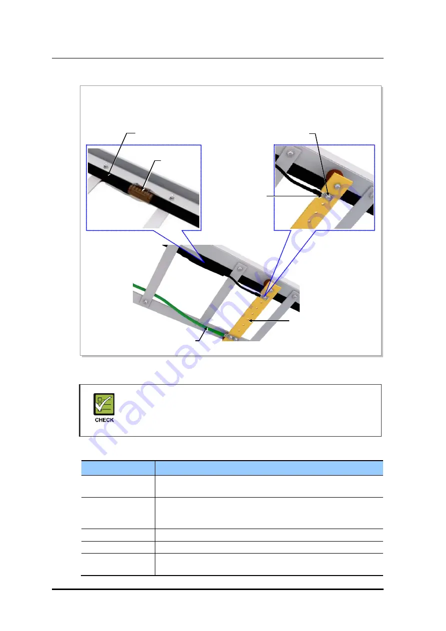
Figure B.4 Feeder Cable Grounding (4)
Check Ground Kit and TGB Specifications
The specifications, clamp, and pressure terminal type of the ground kit and TGB
differ depending on manufacturers. Make sure to check the specifications of the
ground kit and TGB, and identify the installation method before installing it.
Table B.5 TGB Installation Example
Category
Description
TGB Usage
Earth terminal board for feeder cable for grounding in using the feeder
cable of more than 7/8 in.
TGB Location
Lower section of cable rack in feeder cable duck
- less than 65.62 ft (20 m): 1 (Ex. steel tower lower section)
- more than 65.62 ft (20 m): 2 (Ex. steel tower lower and upper section)
Material
Pure copper
Installation Method
Using the insulator to separate from the steel tower electrically
Connection Method
Extract the AWG2, GV 25 mm
2
ground cable to the direction of the floor
and weld it to the tower’s ground cable.
9) After the ground kit has been installed to the feeder line, attach the pressure terminal (1 hole) of the
ground cable connected to the ground kit to the TGB.
10) When attaching the pressure terminal, use M6 × 25L hex. Bolts.
TGB (Tower Ground Bar)
TGB Ground Cable
(AWG2, GV 25 mm
2
× 1C)
M6 × 25L Hex. Bolt (STS304)
Ground kit
7/8 in. Feeder Line
Pressure Terminal
(1 Hole)


