40
6. PCB Diagrams
6. PCB Diagrams
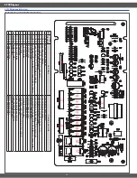
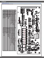
6-1 PCB Diagrams (00Version)
(This Document can not be used without Samsung’s authorization)
⑪
⑫
⑬
⑭
⑮
①
②
③
④
⑥
⑤
⑧
⑨
⑩
⑦
No
.
Parts
Number
Part Name
Function and Rule
1
CN402
Louver switch connector
Connected to louver switch
2
CN301
Gas sensor connector
Connected to gas sensor
3
CN401
Door switch & Hood
T .C
.O connector
Connected to door switch & hood
T .C
.O
4
CN601
Membrane switch connector
Connected to membrane switch
5
CN202
Cook top Lamp,T/T
& V
ent Relay connector
Connected to cook top lamp,
T/T
& V
ent motor
6
CN201
AC Power(LIVE), Oven lamp & Louver relay connector
Connected to
AC Power(LIVE), Oven lamp & Louver motor
7
R
Y21
1
Vent boost relay
Vent motor speed control
8
R
Y209
Vent high relay
Vent motor speed control
9
R
Y210
Vent low relay
Vent motor speed control
10
R
Y208
Turn table relay
Turn table motor control
11
R
Y201
Main relay
Cooling fan, oven lamp & stirrer motor control
12
R
Y207
Louver relay
Louver motor control
13
R
Y206
Lamp bright relay
Cook top brightness control
14
R
Y205
Lamp night relay
Cook top brightness control
15
R
Y202
Inrush relay
Decrease inrush current
16
R
Y204
Power low relay
MWO power control
17
R
Y203
Power high relay
MWO power control
Summary of Contents for SMH8165STE
Page 3: ... 1 Precaution ...


