VIDEO METRIX SWITCHER
User’s Manual
11
VIDEO METRIX SWITCHER
User’s Manual
10
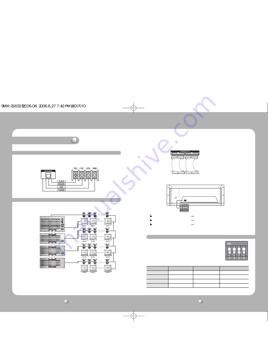
2-2. Matrix Cable
Connection cables are within the matrix; cables may vary slightly.
2-3. Matrix Extension Unit
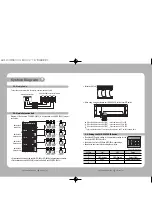
Diagram of Matrix main CPU(SMX-25632) & its extension units’(SME-25632) proper
connection.
• A twisted pair cable must be used for RS -422 or RS -485 data transmission operation.
• Place extension units(SME-25632) under the Matrix Main CPU(SMX-25632).
• The default DIP switch setting is the appropriate setting for the
country the SMX-25632 is sold in.
• See below chart for the OSD and NTSC/PAL mode settings.
• Remove the front cover before setting the switches.
• Extention I/O Port
• When using a matrix extension unit (SME-25632), set the inner DIP switch.
Matrix Keyboard Port
SCC-3100 PORT 3 Connection Terminal
SMX-25632
(Main CPU)
SMX-25632(dip switch)
SME-25632
Extension Unit
SME-25632
Extension Unit
SME-25632
Extension Unit
When the Address is set to 1(ON) sets camera no.65 to 128
When the Address is set to 2(ON) sets camera no.129 to 192
When the Address is set to 3(ON) sets camera no.193 to 256
* To turn address number 3 on, turn both numbers 1 and 2 on at the same time.
2-4. Setting the SMX-25632 DIP Switch
DIP No.
ON
OFF
Detail
1
-
-
-
2
OSD, Korean
OSD, English
Select OSD
3
NTSC
PAL
Select Imaging Mode
4
-
-
-
System Diagram


