background image


Network Video Recorder SNR-6400/3200 

36 

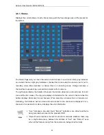
To control the OSD menu, click the 

  buttons at the bottom of the video screen. To 

move between OSD menus and change the settings, use the arrow buttons. To move to a sub 

menu or apply new settings, click the SET button. To move back to the previous menu, click 

the ESC button. Instead of the SET and ESC buttons on the video screen, you may also use 

the 

 and 

 buttons next to the 

 button. For detailed instructions on setting up an 

OSD, please refer to the user manual for the respective camera. 


Note 

The Mic, PTZ preset, and OSD control menus are not compatible with AXIS 

cameras. 


4.5. Playback 

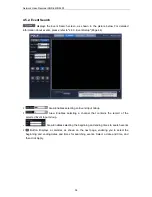
Click 

  at the top of the screen to display the Playback screen. This screen lets you 

watch saved videos. There are two ways to use the Playback option; 

 enables you 

to search and watch videos by the recorded time and date, while 

 lets you view 

videos according to events that have occurred. When connecting to the Playback screen for 

the first time, the Time Search menu appears as the default. 

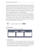
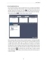
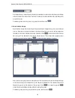
4.5.1. Time Search 


Summary of Contents for SNR-3200

Page 1: ...Network Video Recorder User Manual SNR 6400 3200 ...

Page 2: ......

Page 3: ...d party The product warranty does not extend to any accident neglect alteration or misuse of the product Furthermore this warranty does not cover any components or parts that are not supplied by the manufacturer of this product The product warranty period is for three years from the purchase date However the warranty does not cover any of the following problems and a nominal service fee will be ch...

Page 4: ... experienced personnel self installation by the user is prohibited Self installation by the user may result in fire electrocution and or product malfunctions Please contact your local dealer for assistance with the installation of the product The contents of this manual may change in order to accommodate upgrades in firmware and or software Also the specifications and or design of this product may...

Page 5: ... 2 3 2 Playback Page 14 2 3 3 Config Page 15 2 3 4 System Page 18 Chapter 3 Installation 19 3 1 Installing and Connecting Product 19 3 1 1 Supplying Power and Operating the Product 19 3 1 2 Configuring the Network 19 3 1 3 Internal HDD 20 3 1 4 External HDD 23 3 1 5 Sensor 24 3 1 6 Relays 25 3 1 7 USB 26 3 2 Connecting to the Website 26 3 2 1 Connecting Cable 26 3 2 2 Adding an IP Address 26 3 2 3...

Page 6: ...42 4 6 2 Record Setup 43 4 6 3 Event Setup 44 4 6 4 Camera Setup 47 4 6 5 HDD Setup 51 4 6 6 Network Setup 56 4 6 7 Time Setup 61 4 7 System 63 4 7 1 Upgrade 64 4 7 2 System Log 66 4 7 3 User Setup 69 4 7 4 Backup 70 Chapter 5 LCD Setup 75 5 1 System 76 5 1 1 Checking Firmware Version 76 5 1 2 Turning On Off Beep 76 5 1 3 Relay Off 77 5 1 4 System Update 77 5 1 5 Initializing Settings 78 5 1 6 HDD...

Page 7: ...tup 86 5 4 Removing HDDs 89 5 5 Formatting HDDs 90 5 5 1 Formatting a Single Internal HDD 90 5 5 2 Formatting All Internal HDDs 91 5 5 3 Formatting a Single External HDD 91 5 5 4 Formatting All External HDDs 92 5 5 5 Formatting All HDDs 93 Troubleshooting 94 Product Specifications 96 Product Dimensions 98 ...

Page 8: ......

Page 9: ...ge storage capacity and also comes with a wide variety of user friendly features such as Simultaneous recording and playback capabilities motion detection PTZ pan tilt zoom control password real time voice data recording convenient access permissions setup using Key Lock and maintenance of up to 10 000 event lists and log files 1 1 Safety Precautions Warning The following information or instructio...

Page 10: ...malfunction shock or other dangers Do not disassemble or attempt to fix or alter the product yourself 3 Do not clean the product with water paint thinner or other organic solvent as doing so may cause product malfunctions and or electric shock When cleaning the product use a dry cloth to wipe the exterior of the device Caution Misuse or wrongful operation of the item may result in injury or damage...

Page 11: ...unction abnormally 3 Arbitrarily adding a hard disk to the product will void your product warranty 3 This product is not an anti theft or fire prevention device the manufacturer is not responsible for any damage to property or personnel that may occur Caution Samsung Techwin recommends the installation of a UPS Uninterrupted Power Supply with all its recording products Samsung Techwin cares for th...

Page 12: ...corder SNR 6400 3200 10 1 2 Product Contents The contents of this product are as shown below Power Cord Key Rack Mount and Fixture Screws HDD Fixture Screws User s Manual Quick Reference Guide Cross Cable HDD Tray 4EA ...

Page 13: ...nternal HDD2 is not functioning properly 5 Internal HDD3 A blue indicator means that Internal HDD3 is installed and functioning normally A red indicator means that Internal HDD3 is not functioning properly 6 Internal HDD4 A blue indicator means that Internal HDD4 is installed and functioning normally A red indicator means that Internal HDD4 is not functioning properly 7 EXTERNAL HDD1 A blue indica...

Page 14: ...ace properly 16 LINK ACT2 A blinking blue indicator means that a network cable is properly connected to the Source Ethernet Port and data communication is taking place properly 17 LINK ACT3 A blinking blue indicator means that a network cable is properly connected to the Storage Ethernet Port and data communication is taking place properly 18 POWER A red indicator means that the product is powered...

Page 15: ...Button Turns on or off the product 7 Source Ethernet Port A network port that connects the product to the video camera 8 SENSOR IN RELAY OUT Used to connect a sensor or alarm 9 GROUND A terminal that is used to ground the frame to an external device 10 Storage Ethernet Port Used to connect NAS Network Attached Storage within the same network 11 eSATA Port1 Used to connect an external HDD 12 eSATA ...

Page 16: ...s for the product 2 3 1 Monitoring Page Main Menu Sub Menu Default Setting Auto Sequence Off Display Mode 16Ch display Group 1 Channel 1 Info On DIT Off PT ZF PT Activated OSD Off PTZ speed 3 2 3 2 Playback Page Main Menu Sub Menu Default Setting Time Channel Calendar Time Event Event Type Channel Date Time ...

Page 17: ...g Input Group Active Inactive Pre Recording Time Post Recording Time own event All frames I frames 5 Sec 5 Sec Record Button Time Table Normal Record selected Always Normal Record Event Setup Main Menu Sub Menu Default Setting Local Sensor Type Sensor1 Sensor2 Normal Open Normal Open Event Group Input Group Output Group Action Group ...

Page 18: ...le Channel Name Model Connection Type IP Connection Port ID Password Picture Type ATC Mode Video Quality Video Resolution Video Framerate Disable Ch01 Ch02 Ch03 Static IP 0 0 0 0 4000 MPEG Off High D1 10 HDD Setup Main Menu Sub Menu Default Setting HDD Repeat Recording On RAID Mode Normal NAS Configuration Nas Port Use Name Default Folder IP ID Password Nas1 Disable 0 0 0 0 ...

Page 19: ...s com Source Ethernet Port Connection Type IP Address Subnet Mask Gateway Static IP 0 0 0 0 0 0 0 0 0 0 0 0 Source DHCP Server Use IP Range Disable 0 0 0 0 0 0 0 0 Storage Ethernet Port Connection Type IP Address Subnet Mask Gateway Static IP 0 0 0 0 0 0 0 0 0 0 0 0 DNS DNS1 DNS2 168 126 63 1 168 126 63 2 RTP RTSP Use RTSP RTSP Port RTP Port Use Multicast Multicast Address Disable 554 4000 Disable...

Page 20: ... NTP Use Client Use Server Public Server1 Address Public Server2 Address Public Server3 Address Public Server4 Address Public Server5 Address Disable Disable pool ntp org asia pool ntp org europe pool ntp org north america pool ntp org time nist gov 2 3 4 System Page User Main Menu Sub Menu Default Setting Admin Password 11111111 User ID Password Authority user 22222222 Only Monitoring is Allowed ...

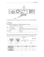
Page 21: ... product When the system has encountered an error and you can t turn it off normally you can press and hold down the power switch for five seconds to force the system to shut down 3 1 2 Configuring the Network The following picture is an example of a network diagram using the SNR 6400 3200 The 3 network ports on the product back panel are for a computer camera and NAS Network attached Storage Plea...

Page 22: ...work Video Recorder SNR 6400 3200 20 3 1 3 Internal HDD Open the HDD Bay as shown below to add remove or replace an internal HDD Press PUSH to open the Locking Door Turn Key Lock counterclockwise to unlock ...

Page 23: ...D Door While pressing the HDD Hook down pull on the handle to pull out the SATA Bracket Unscrew the fixture screws on the SATA Bracket before removing the HDD fasten the screws securely after you insert the HDD in the SATA Bracket ...

Page 24: ...Network Video Recorder SNR 6400 3200 22 Make sure that the SATA Bracket is pushed back all the way in the HDD Bay and close the HDD Door Turn Key Lock clockwise to lock Close the Locking Door ...

Page 25: ... to 5 4 Removing HDDs Page 89 Caution To lock the HDD door please make sure to turn Key Lock clockwise completely 3 1 4 External HDD The SNR 6400 3200 supports an eSATA interface for connecting external storage devices four eSATA ports are located on the rear panel The product can have up to 20 TB of storage capacity by utilizing the internal HDDs and eSATA ports Based on 1TB data capacity per HDD...

Page 26: ...nal HDD 4 Turn on the product The eSATA cable is not included with the product For a list of compatible HDDs please refer to Recommended HDDs Page 95 3 1 5 Sensor The following are specifications and operating conditions for sensor input Spec Number of Input Circuits 2 Input Types N C N O Supported Sensor Types Dry Contact sensors Connection Type Attach stripped wire connections to the terminal bl...

Page 27: ...Number of Input Circuits 2 Relays Output Types Dry Contact Connection Type Attach stripped wire connections to the terminal block Power DC 30V 1A AC 125V 0 5A When connecting the relay outputs first determine the attributes of the device to be connected Normal Open or Normal Close then connect the device by referring to the diagram below RELAY OUT 1 NC CM NO Normal Close O O Common O Normal Open O...

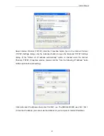
Page 28: ...t panel Please refer to 5 1 4 System Update Page 77 3 2 Connecting to the Website 3 2 1 Connecting Cable Press PUSH on the front panel to open the Locking Door then connect a PC to the Front Panel Network Port with the supplied crossover cable as shown in the illustration below When using a hub to connect the product to a computer you may use a normal LAN cable instead of a cross over cable 3 2 2 ...

Page 29: ...ettings dialog If the Obtain an IP address automatically option is checked under the Internet Protocol TCP IP Properties window please click the Use the following IP address radio button option before proceeding Click Add under IP addresses then enter 192 168 1 xxx The SNR 6400 3200 uses 192 168 1 100 as the IP address you cannot use the address for your computer s internal IP address ...

Page 30: ...3200 28 3 2 3 Connecting and Changing Settings Type 192 168 1 100 in your Internet browser address bar then press Enter In the login window enter admin as the User ID and 11111111 for the Password Click Login to connect to the product ...

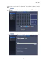
Page 31: ... product for the first time no video displays as no network or camera is set up Clicking at the top of the screen directs you to a new page as shown in the screenshot below Clicking directs you to a new page as shown in the screenshot below ...

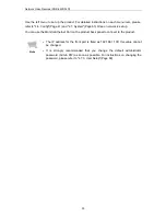
Page 32: ...network is set up You can use the Monitor Ethernet Port on the product back panel to connect to the product Note The IP address for the front port is fixed as 192 168 1 100 this value cannot be changed It is strongly recommended that you change the default administrator password Admin PW as soon as possible For instructions on changing the password please refer to 4 7 3 User Setup Page 69 ...

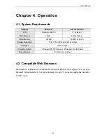
Page 33: ...esolution 1024 x 768 32bit color or higher Hard Disk 1GB or higher Operating System Windows XP Professional Windows Vista Business Miscellaneous DirectX 9 0 or higher 4 2 Compatible Web Browsers Web Viewer is optimized for use with Microsoft Internet Explorer 6 0 or higher You must have Microsoft Internet Explorer 6 0 or higher installed on your PC to ensure trouble free operation of Web Viewer ...

Page 34: ... to 4 7 3 User Setup Page 69 Note To connect to the product using the front network port please make sure to enter 192 168 1 100 To connect to the product using the rear Monitor Ethernet Port make sure to enter the IP address assigned to the port The connecting port and computer must be within the same network For an HTTP port number with any value other than 80 then the access address is http IP ...

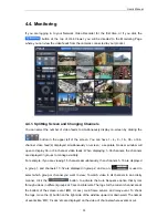
Page 35: ...64 channel video feeds When displaying 1 36 channels the channels are displayed in groups to manage visibility For example if you are viewing 16 channels simultaneously then channels 1 16 are displayed in group 1 and channels 17 32 are displayed in group 2 and so on is used to select which group or channel you want to view To watch video in all channels in an orderly manner click the button to act...

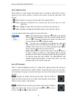
Page 36: ...ly selected channel An icon indicates which camera you are currently speaking through can also be clicked to adjust the volume at the camera Preset Displays on a channel video screen Clicking lets you to select a preset A Preset is a pre selected angle and zoom operation for a PTZ camera Selecting a preset reverts the camera to the previous angle and zoom settings The SNR 6400 3200 only supports l...

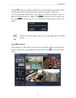
Page 37: ...ge A total of 6 different PTZ speed levels are available Click to decrease the PTZ speed by one level and to increase it by one 1 is the slowest PTZ speed setting and 6 is the fastest Note The PTZ control and preset options are only compatible with PTZ enabled cameras 4 4 4 OSD Control When clicking on a channel video the video screen is outlined in orange to indicate that it is selected To displa...

Page 38: ...button For detailed instructions on setting up an OSD please refer to the user manual for the respective camera Note The Mic PTZ preset and OSD control menus are not compatible with AXIS cameras 4 5 Playback Click at the top of the screen to display the Playback screen This screen lets you watch saved videos There are two ways to use the Playback option enables you to search and watch videos by th...

Page 39: ...time of the current video DIT Button Activates or disables the Deinterlace option for the current video REW and FFW Buttons Rewind fast forward and adjust the current video play speed While a video is playing the buttons change to and indicating the play direction and speed The adjusted play speeds are 1x 2x 4x and 8x backward and forward Each time the REW or FFW button is pressed the play speed c...

Page 40: ...Page 44 Area Enables selecting an Event Input Group Area Enables selecting a channel that contains the record of the selected Event Input Group Area Enables selecting the beginning and ending times to search events Button Displays a calendar as shown on the next page enabling you to select the beginning and ending dates and times for searching events Select a date and time and then click Apply ...

Page 41: ...he screenshot below To play a video click on a result To check all the 10 results move the in the right of the screen upward and downward displays all search results on the left side of the page 10 Search results are displayed at a time Clicking on an item automatically plays a video saved in the selected time and move to the previous or next results page moves to the previous screen ...

Page 42: ...searched Sound Button Turns audio on or off for the current video Capture Button Captures a screenshot of the current screen in JPG format Info Button Displays the channel name and recorded time of the current video DIT Button Activates or disables the Deinterlace option for the current video REW and FFW Buttons Rewind fast forward and adjust the play speed of the current video While a video is be...

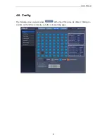
Page 43: ...User s Manual 41 4 6 Config The following screen appears when at the top of the screen is clicked Clicking on a button on the left menu directs you to the corresponding page ...

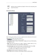
Page 44: ...channels the bitrate video loss and audio loss for both Live and Record modes The top pane displays information for the current channel while the bottom displays information for all channels When selecting a channel that is Connected or Recording the bitrate as well as video and audio losses for the channel are displayed For a channel in Connection Error state it displays the error information Not...

Page 45: ...the left of the screen to choose its video recording method Select a channel on the left side of the screen to choose its video recording method To choose time and a method of saving a video on each day select one of or and then drag the cursor in the bottom timetable to make a selection Different colored blocks of hours and days indicate different record modes Upon selecting the name of the recor...

Page 46: ...vent is detected For Normal Record and Event Record Active All frames I frames and 2 I frames are available For Event Record Inactive All frames I frames 2 I frames and No Record are available Choose All frames to store all video feeds from the camera while I frame stores only the 1 frame of the video feed per 1second Choosing 2 I frames stores only the I frame of the video feed per 2 seconds No R...

Page 47: ...e Input Group or Output Group pane The list below the panes displays the channel camera names along with the product To display available Input Event or Output Event sources double click on a camera or the product For Input Group available options include Sensor and MD Motion Detector and Relay E mail and Beep for Output Group For more information about input and output signals for cameras please ...

Page 48: ...ent Input Group occurs all the responses included in the Event Output Group are included Click under Event Action Group list and you ll be directed to the screen shown below This screen also appears when selecting a group and then clicking or simply double clicking on a group First enter a new group name in Group Name Then select Event Input and Output Groups in the Input Group and Output Group li...

Page 49: ...annel Name is displayed on the top of the Monitoring and Playback screens Model Select the model number for a camera In addition to network cameras you can choose network video servers such as the SNS 100 SNS 400 etc Connection Type Select the connection type for a camera between Static IP and DDNS To use Static IP enter the IP address and connection port for a camera To use DDNS enter the DDNS se...

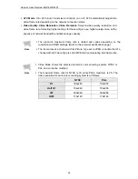
Page 50: ...The product s maximum frame rate is limited and varies depending on the resolution and RAID settings Refer to the product specifications page The frame rate of a channel with its Picture Type set to JPEG is double that of a channel with its Picture Type is set to MPEG when calculating total frame rate Note Video Mode shows the selected camera s color encoding system NTSC or PAL and cannot be modif...

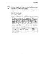
Page 51: ...alf D1 and CIF resolutions In this case please use the following chart to determine Video Mode and Video Resolution For instance if you want to use CIF video resolution for an AXIS camera check if 352x240 320x240 or 352x288 is listed under the resolution in the chart If one of the sizes is available that means that you can use the resolution If a selected resolution is not applicable the product s...

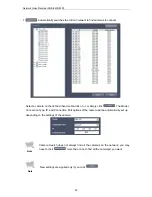
Page 52: ...lick on it or simply click The Model Connection Type IP and Connection Port options of the camera will be automatically set up depending on the settings of the camera Note Camera Search does not always find all the cameras on the network you may have to click more than once to find all the camera s you want Note New settings are applied only if you click ...

Page 53: ...ernal HDDs are displayed as RAID instead of Internal and their model names are replaced by the raid mode RAID1 MODE or RAID5 MODE While an HDD is being formatted an HDD is in the disk checking process and a new RAID mode is being configured Formatting Testing and Building are displayed instead of the device model names Set Repeat Recording to On and the system will automatically erase the oldest r...

Page 54: ...ID Mode menu you can change the system RAID settings To change the settings select Normal RAID1 or RAID5 and then click on the right Normal is the non RAID mode Upon applying new RAID settings the system automatically reboots itself you will be disconnected from Web Viewer The system requires approximately 2 minutes to reboot and establish a network connection While the new RAID settings are being...

Page 55: ...cess Note RAID Redundant Array of Independent Disks helps you keep data safe in case the system HDD is damaged Selecting RAID1 mode configures HDD1 and HDD2 as one array and HDD3 and HDD4 as the other array RAID1 uses 2 physical HDDs as 1 functional HDD For instance configuring HDD1 and HDD2 while each is equipped with a 500GB HDD to RAID1 displays the system s functional HDD as one 500GB RAID In ...

Page 56: ...ically deletes all data in the HDDs of the product and new video files are not saved until the new RAID mode is completely configured When the product is turned off abnormally i e by pulling the AC power adapter out and then turned on the product may reconfigure its RAID settings automatically to ensure the integrity of saved data While a new RAID mode is being configured existing data is not lost...

Page 57: ...to the NAS HDD you must change settings to Disable and then change back to Enable If a connected NAS HDD becomes disconnected from the product its status in the HDD list changes from Connected to Not Connected In this case the product automatically connects to the NAS HDD if the problem is resolved The status of the HDD then reverts to Connected The NAS data saving speed is slower than internal an...

Page 58: ...d enter the IP address subnet mask and gateway to use Choose DHCP if a DHCP server is connected to the network you want to connect to the DHCP server will automatically assign an IP address for you Note If you are using PPPoE or DHCP you will find the IP address currently assigned to your product in Assigned IP you cannot set Assigned IP yourself Changing the network connection method from PPPoE t...

Page 59: ...een is to apply ATC to the communication between your computer and the product Monitor Ethernet Port supports DDNS By registering your product with a DDNS server you can connect to the Monitor Ethernet Port from outside by using the DDNS server ID instead of the product s IP address If you are using either PPPoE or DHCP to connect to the Monitor Ethernet Port you ll be assigned a n ew IP address e...

Page 60: ...rt may terminate the connection If this happens you must use the new address to connect to the product All ports use the same DNS server you can have up to two DNS servers DNS1 is used as the default and DNS2 is used when DNS1 is unavailable Using RTP RTSP lets you watch the video of the SNR 6400 in the monitoring system without using Web Viewer To use RTP RTSP select Enable in the Use RTSP menu a...

Page 61: ...depending on its version Version 0 9 8a or higher 1 In the Network Setup page select Enable in the Use RTSP menu To use Multicast select Enable in the Use Multicast menu 2 Install and run VLC Media Player in your computer Under the Media menu select Open Network or simply use the shortcut key Ctrl N Select RTSP under Protocol 4 Depending on the type of a video enter an address as from the examples...

Page 62: ...eo from Channel 1 that is recorded on April 5 2009 at 9 30am You can register your e mail address in the Network Setup screen so your product can notify you with an e mail when a defined Event occurs Please Refer to 4 6 3 Event Setup Page 44 Enter an outgoing e mail server address under SMTP Server Name and an e mail address under E Mail To If your mail server requires authentication for sending e...

Page 63: ...change its value The up down button can be used instead of the keyboard to change the current time To display a calendar click in the date window The current date of the product is highlighted in blue The current date of the product is highlighted in blue The current date of your computer is circled in red on the calendar as well as written on the bottom of the calendar To move to the previous or ...

Page 64: ...rk NTP client automatically communicates with registered NTP servers to adjust its time setting To use an NTP server other than the default one change Public Server Address Note Changing the GMT settings automatically changes Current Time Synchronizing the time settings of the NTP server and the product may take a while if you change NTP client settings from Disable to Enable Updating the time set...

Page 65: ...4 7 System The following page appears when selecting at the top of the screen By clicking on one of the buttons on the left of the screen you can go to the page that corresponds to the function described on that button ...

Page 66: ...f the system and enables resetting the settings F W Version At top of the screen is the current firmware version Click for more details as shown in the screenshot below F W Upgrade To upgrade the firmware of the product click under the F W Upgrade menu and then select a firmware file to upgrade ...

Page 67: ...e settings of the Record Event Camera and User menu For more information about the default settings value please refer to 2 3 Default Settings Page 14 Import Export Configuration You can save the product s current settings as a file and then use the file to restore the settings in the future To save the current settings of the product as a file click the button and then set the filename and path T...

Page 68: ... To see the history of the system settings changes or event group changes double click on a log file of the Configuration Changed or Event Group Created type The details appear as shown in the screenshot below and moves to the previous or next page To move directly to a page enter the page number in the text box and then click To save a system log file to your computer click Note Up to 10 000 logs...

Page 69: ...roup Created An Event Group was created Event Group Deleted An Event Group was deleted Key Lock On Key Lock was locked Key Lock Off Key Lock was unlocked HDD Test HDD disk checking was performed Log File Export A log was exported Firmware Update Firmware was updated Set Default Set Default was executed via Web Viewer Factory Reset Factory Reset was performed using the front panel button RAID Error...

Page 70: ... Sensor Sensor Setup Relay Relay Output V Loss Video was lost from a camera Monitoring Connection The Live screen was connected Input Group An Event included in Input Group occurred Output Group An Event included in Output Group occurred Intelligence An Event specified in the Intelligence feature occurred ...

Page 71: ...st permissions level In addition to the Admin account you can set up one user account with limited permissions The User account is granted permissions by the Admin under the Authority menu Monitoring and Playback refer to the menus used when accessing the product via Web Viewer PTZ OSD Control refers to the connected cameras PTZ and OSD functions Refer to 4 4 3 PTZ Control Page 34 and 4 4 4 OSD Co...

Page 72: ...o select a recorded period for backup video files click the button Selecting a channel in the Channel dropdown menu displays the channel s recorded period in the From and To panes under the Date Time menu Select the beginning and ending time of the backup video files in the From and To panes and then click the button to start backing up the video files ...

Page 73: ...ing the button selects all search results Note The maximum searchable period is 7 days If more than 500 event video files are recorded within a selected search period data saved after a day for which 500 or more accumulated video files are recorded is not searched For example if video files are searched from 10 th to 15 th and 800 accumulated video files are saved by 11 th the program will not sea...

Page 74: ...o change the download folder click the button Backing up video files automatically creates a sub folder under the designated download folder The sub folder is named after the product IP address e g SNR 6400_Backup_192 168 1 100 and contains the backup video files Backup video files are playable with SLiM Player To download SLiM Player click the button at the bottom of the page Note The buttons and...

Page 75: ...d channels 8 Time Info Display the running time of a video file that is being played 9 Play Speed Adjust the play speed of the player 1x 2x 4x and 8x 10 Play Options Play options Skip back a frame Play backward Pause Play forward Skip forward a frame 11 ScreenSize Adjust the screen size of the player 1x 2x Full Screen 704x240 and 704x288 videos can be enlarged by 2x without degrading image quality...

Page 76: ......

Page 77: ...ocated to the right you can check the system s status and change some of its settings Up and Down Buttons Used to move between menus and select letters and numbers in text mode Left and Right Buttons Used to move the cursor in text input mode ENTER Button Moves to the next phase ESC Button When pushed it moves back to the previous phase When holding it down for 2 seconds or longer it moves to the ...

Page 78: ...picture provided for your reference the firmware version differs depending on the model 5 1 2 Turning On Off Beep You can turn the beep of the front panel buttons on or off using this menu item Under System select 2 Key Beep On Off and then press ENTER Selecting 1 On and pressing Enter turns on the beep Selecting 2 Off and pressing Enter turns off the beepIn each case the following messages appear...

Page 79: ...st be connected to the USB port on the rear panel The firmware update file must have a file name that starts with snr and a filename extension bin The firmware update file must be located in the root directory of the flash drive If more than one update file exists on the flash drive the firmware update might not install properly To download the latest firmware files please visit Support Download C...

Page 80: ...g Settings Under System select 5 Factory Reset and then press ENTER A message appears on the display prompting you to confirm that you wish to reset all configurations to their defaults Upon pressing Enter the following messages appear while settings are being initialized When initialized the system reverts to the factory default settings To move back to a previous phase press ESC To cancel the in...

Page 81: ...ys a message asking if you really want to perform disk checking for the selected HDD When pressing ENTER the following message appears as the disk checking process is initiated Once the process is complete the screen displays the check results The check results stay on the screen until you click a button HDD test result 0 bad block Are you sure Yes Enter No Esc Record on this HDD will be stopped E...

Page 82: ...f and then press Enter The following message appears prompting you for if you really want to shut down the system Upon pressing Enter the following messages appear while the system shuts down To move back to the previous phase press ESC To cancel shutting down and move back to the main screen hold down ESC for 2 seconds or longer These messages also appear when the power switch on the product back...

Page 83: ...tup The Monitor Ethernet Port is a port used to connect your computer to the product Under Network Setup select 1 Monitor Ethernet Port and press ENTER Use one of the first 3 options to set an IP address for the Monitor Ethernet Port Selecting menu item 4 lets you to use DDNS instead of an IP address Static IP Setting Press and to select 1 Use Static IP and then press Enter IP Address 0 0 0 0 3 Us...

Page 84: ...nger Note The DNS1 address can be set under Monitor Ethernet Port Port Static IP The DNS 2 address is under Source Port Static IP Once set these DNS servers are used by all ports DNS1 is used as the default and DNS2 is the backup DHCP Client Setup Press and to select 2 Use DHCP Client and then press Enter Pressing Enter moves to the next screen as Monitor Ethernet Port is updated to use DHCP To mo...

Page 85: ...e new settings and move back to the main screen hold down ESC for 2 seconds or longer Note Changing the network connection method from PPPoE to DHCP or Static IP automatically reboots the system DDNS Setup Press and to select 4 Use DDNS and then press Enter The default DDNS server is www samsungipolis com To use a DDNS server other than iPOLiS use and to select from alphanumeric characters a z and...

Page 86: ...tup select 2 Source Ethernet Port and then press ENTER Use one of the first 3 options to set an IP address for the Source Ethernet Port For detailed instructions on the port setup please refer to Static IP DHCP Client and PPPoE setups under 5 2 1 Monitor Ethernet Port Setup Page 81 Selecting menu item 4 lets you use the DHCP Server option DHCP Server Setup Press and to select 4 Use DHCP Server and...

Page 87: ... 5 2 3 Storage Ethernet Port Setup The Storage Ethernet Port is used for communication between the product and NAS Under Network Setup select 3 Use Storage Ethernet Port and then press ENTER Use one of the 3 options to set an IP address for Source Ethernet Port For detailed instructions on the port setup please refer to Static IP DHCP Client and PPPoE setups under 5 2 1 Monitor Ethernet Port Setup...

Page 88: ...n corresponding to the selected mode Press Enter to change the HDD mode to the selected mode To move back to the previous phase press ESC To cancel the new settings and move back to the main screen hold down ESC for 2 seconds or longer While the new RAID mode is being configured the following messages appear in order informing of the progress and remaining time Rebooting system is in Progress Prep...

Page 89: ... damaged Selecting RAID1 configures HDD1 and HDD2 as one array and HDD3 and HDD4 as the other array RAID1 uses 2 physical HDDs as 1 functional HDD For instance configuring HDD1 and HDD2 while each is equipped with a 500GB HDD to RAID1 displays the system s functional HDD as one 500GB RAID In the RAID1 mode no data is lost even if one of the two HDDs of a There are not enough HDD to build RAID5 Che...

Page 90: ...only for internal HDDs Building a RAID mode using 4 x 500GB HDDs takes approximately 3 hours for RAID1 and 4 hours for RAID5 Caution Changing the RAID settings to a new mode automatically deletes all data in the HDDs of the product and new video files are not saved until the new RAID mode is completely configured When the product is abnormally turned off i e by pulling the AC power adapter out and...

Page 91: ...ove the HDD from the product When selecting an HDD that is not available or connected the following message appears Note The number for an internal HDD or external HDD bay is determined depending on which product port that you connect to Available numbers are 1 2 3 and 4 from the upper left and right to the bottom left and right Please Refer to Chapter 2 Part Names Page 11 Remove Ext Bay 1 DONE Ch...

Page 92: ...D and then press Enter Use the v buttons to select the number for the HDD to format then press ENTER Upon pressing Enter the following messages appear while the selected HDD is being formatted To move back to the previous phase press ESC To cancel formatting and move back to the main screen hold down ESC for 2 seconds or longer HDD Format DONE Formatting HDD is in Progress Format HDD 1 Yes Enter N...

Page 93: ...ous phase press ESC To cancel formatting and move back to the main screen hold down ESC for 2 seconds or longer 5 5 3 Formatting a Single External HDD Under HDD Format select 2 External HDD and then press Enter Use and to select the number for the external HDD bay containing the HDD to format then press Enter Check HDD to format Please Try Again Internal HDD 1 is empty 1 Individual HDD 2 All HDD i...

Page 94: ...longer When selecting an HDD that is not available or connected the following message appears 5 5 4 Formatting All External HDDs Under HDD Format select 2 External HDD and then press Enter Use and to select the number for the external HDD bay containing the HDD to format and then press Enter 2 Select All HDD in Bay and then press Enter External Bay 1 is not connected External Bay 1 is not connecte...

Page 95: ...s or longer 5 5 5 Formatting All HDDs Under HDD Format select 3 All HDD and then press Enter Upon pressing Enter the following messages appear while all HDDs both internal and external are being formatted To move back to the previous phase press ESC To cancel formatting and move back to the main screen hold down ESC for 2 seconds or longer HDD Format DONE Formatting HDD is in Progress HDD Format D...

Page 96: ... the HDD Setup page z Check the free space of HDDs z Check video recording setup 4 Stored video does not play z Check video recording setup 5 Video is too bright or too dark z Check camera setup 6 Front panel buttons do not work z Check power z Check Key Lock status 7 Network does not function z Check network cable connection z Check Recorder s IP setup z Check PC s IP setup z Run Ping Test z If W...

Page 97: ...uid has entered the product z You have spilled liquid into the product or foreign material has entered the product z The product does not work as specified in this instruction manual z The product has been dropped and severely damaged z There is a noticeable degradation in the performance of the product Recommended HDDs Please use HDD products from the following manufacturers with your Samsung Net...

Page 98: ... Up to 960fps 704 x 240 Up to 1 920fps 704 x 240 Up to 960fps 352 x 240 Record Rate PAL Up to 1 152fps 704 x 576 Up to 480fps 704 x 576 Up to 1 600fps 704 x 288 Up to 800fps 704 x 288 Up to 1 600fps 352 x 288 Up to 800fps 352 x 288 Mode Manual Schedule Normal Event Overwrite Modes Continuous Pre alarm Up to 5sec Post alarm Up to 60sec Search Playback Search Mode Time Event Calendar Playback Functi...

Page 99: ...orts Supported IP Cameras Samsung Techwin network products AXIS network cameras VAPIX MPEG4 Modes limitted some functions GENERAL Electrical Input Voltage 100 240 V AC 10 50 60 Hz Auto ranging Power Consumption Max 110W with 1xHDD Max 130W with 4xHDD Environmental Operating Temperature 5 C 40 C 41 F 104 F Humidity 0 RH 60 RH Mechanical Dimensions WxHxD 430 x 88 x 501 mm 16 92 x 3 46 x 19 73 Weight...

Page 100: ...Network Video Recorder SNR 6400 3200 98 Product Dimensions ...

Page 101: ...e is permitted to copy and distribute verbatim copies of this license document but changing it is not allowed Preamble The licenses for most software are designed to take away your freedom to share and change it By contrast the GNU General Public License is intended to guarantee your freedom to share and change free software to make sure the software is free for all its users This General Public L...

Page 102: ...prietary To prevent this we have made it clear that any patent must be licensed for everyone s free use or not licensed at all The precise terms and conditions for copying distribution and modification follow TERMS AND CONDITIONS FOR COPYING DISTRIBUTION AND MODIFICATION 0 This License applies to any program or other work which contains a notice placed by the copyright holder saying it may be dist...

Page 103: ... and telling the user how to view a copy of this License Exception if the Program itself is interactive but does not normally print such an announcement your work based on the Program is not required to print an announcement These requirements apply to the modified work as a whole If identifiable sections of that work are not derived from the Program and can be reasonably considered independent an...

Page 104: ...ed not include anything that is normally distributed in either source or binary form with the major components compiler kernel and so on of the operating system on which the executable runs unless that component itself accompanies the executable If distribution of executable or object code is made by offering access to copy from a designated place then offering equivalent access to copy the source...

Page 105: ...section is intended to apply and the section as a whole is intended to apply in other circumstances It is not the purpose of this section to induce you to infringe any patents or other property right claims or to contest validity of any such claims this section has the sole purpose of protecting the integrity of the free software distribution system which is implemented by public license practices...

Page 106: ...AUSE THE PROGRAM IS LICENSED FREE OF CHARGE THERE IS NO WARRANTY FOR THE PROGRAM TO THE EXTENT PERMITTED BY APPLICABLE LAW EXCEPT WHEN OTHERWISE STATED IN WRITING THE COPYRIGHT HOLDERS AND OR OTHER PARTIES PROVIDE THE PROGRAM AS IS WITHOUT WARRANTY OF ANY KIND EITHER EXPRESSED OR IMPLIED INCLUDING BUT NOT LIMITED TO THE IMPLIED WARRANTIES OF MERCHANTABILITY AND FITNESS FOR A PARTICULAR PURPOSE THE...

Page 107: ...ich is not otherwise based on the Library Defining a subclass of a class defined by the Library is deemed a mode of using an interface provided by the Library A Combined Work is a work produced by combining or linking an Application with the Library The particular version of the Library with which the Combined Work was made is also called the Linked Version The Minimal Corresponding Source for a C...

Page 108: ...each copy of the object code that the Library is used in it and that the Library and its use are covered by this License b Accompany the object code with a copy of the GNU GPL and this license document 4 Combined Works You may convey a Combined Work under terms of your choice that taken together effectively do not restrict modification of the portions of the Library contained in the Combined Work ...

Page 109: ...ice if you do both of the following a Accompany the combined library with a copy of the same work based on the Library uncombined with any other library facilities conveyed under the terms of this License b Give prominent notice with the combined library that part of it is a work based on the Library and explaining where to find the accompanying uncombined form of the same work 6 Revised Versions ...

Page 110: ...Network Video Recorder SNR 6400 3200 108 acceptance of any version is permanent authorization for you to choose that version for the Library ...

Page 111: ......

Page 112: ......
Reviews: