background image

COLOR CCD CAMERA

User Guide

10

COLOR CCD CAMERA

User Guide

11

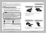
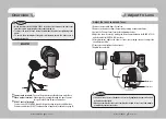
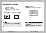
 •   When you adjust to the ZOOM & FOCUS of the lens, Please remove the front cover 

from the camera, by turning the cover counterclockwise.

 •  To adjust the zoom & focus loosen the individual levers before tightening them 

again.

 •  To ensure the weatherproof integrity is maintained, ensure the front cover is 

tightened correctly.

Notes

Overview

BACK


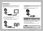
Power input terminal : 

Connect the power as specified for each model here.

9


Video output terminal :  

Video signals are output through this port. Connect 

this port to the Video IN port of a monitor.


RS-485 control terminal : 

You can control SETUP MENU through this port by using external controllers like a 

Remote controller that RS-485 Communication is supported. For details, see page 14. 

Adjust to Lens

Adjust the lens's zoom and focus.

1. Remove the sunshield from the camera.
2. Remove the front cover from the camera by turning it counterclockwise.
3. Unlock the Zoom or Focus lever before adjusting the lens.
4.   Adjust the zoom & focus by moving the lever counterclockwise for (NEAR & TELE) 

and clockwise for (WIDE & FAR) position.

5.   After adjustment, tighten the zoom or focus levers, taking care not to adjust the 

zoom/focus position.

6. Please, close and tighten the front cover.
7.Replace the sunshield.

 •  If the front cover is cross threaded or not correctly tightened the camera housing 

will not be weatherproof.

 •  When you combine the front cover, combine the triangle of front cover and triangle 

of main body confront each other.

Notes

SOC-4160

SOC-4160

SOC-4160

SOC-4160

SOC-4160

Front cover

Focus lever

ZOOM lever

8

9

Summary of Contents for SOC-4160

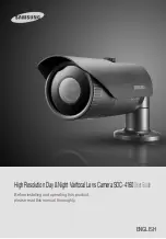
Page 1: ...Before installing and operating this product please read this manual thoroughly ENGLISH HighResolutionDay NightVarifocalLensCameraSOC 4160UserGuide ...

Page 2: ...portant operating and maintenance servicing instructions in the literature accompanying the appliance INFORMATION This equipment has been tested and found to comply with limits for a Class A digital device pursuant to part 15 of the FCC Rules These limits are designed to provide reasonable protection against harmful interference when the equipment is operated in a commercial environment This equip...

Page 3: ...lent Sensitivity The built in high sensitivity COLOR CCD enable a clear image even in 0 15Lux COLOR 0 0003Lux SENS UP or lower illumination High Resolution By adopting a diagonal 6mm 1 3 410 000 NTSC pixel 470 000 PAL pixel SONY CCD the camera produces clear picture quality with a horizontal resolution of 600TV lines for color and a horizontal resolution of 700TV lines for BW mode SSDR Samsung Sup...

Page 4: ...the EU RoHS Directive Warnings Cautions Warning Attention Special Mark Messages Notes Please make sure the product is installed appropriate places where secured from flood such as under the eaves to operate properly This product is certified as IP66 standard However if there is any flood concerns it is highly recommended to use an outdoor Housing When you install the camera inside an outdoor Housi...

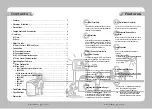
Page 5: ...amera Notes Precautions Overview Components and Accessories 7 2 FRONT Camera Sunshield 2 Sunshield adaptor Fixing the sunshield onto the camera 3 Focus lever Set focus of lens by turn the focus lever 4 Zoom lever Set zoom magnification of lens by turn the zoom lever 5 Front cover 6 Function Setup Switch Display the menu on the screen and move the cursor to four directions to confirm status or afte...

Page 6: ...emote controller that RS 485 Communication is supported For details see page 14 Adjust to Lens Adjust the lens s zoom and focus 1 Remove the sunshield from the camera 2 Remove the front cover from the camera by turning it counterclockwise 3 Unlock the Zoom or Focus lever before adjusting the lens 4 Adjust the zoom focus by moving the lever counterclockwise for NEAR TELE and clockwise for WIDE FAR ...

Page 7: ...V 500mA AC 24V 500mA Please check the standard power requirement before connecting the power RecommendAC24A 500mA adaptor for a long distance Connecting to Power When the resistance value of copper wire is at 20 C 68 F Copper wire size AWG 24 0 22mm2 22 0 33mm2 20 0 52mm2 18 0 83mm2 Resistance value Ω m 0 078 0 050 0 030 0 018 Voltage drop V m 0 028 0 018 0 011 0 006 As shown in the table above vo...

Page 8: ...coaxial communication please use a video amp intended for coaxial communications Regular video amps do not transfer coaxial signals Notes Using RS 485 communication will enable you to control the OSD menu from a SAMSUNG TECHWIN System Controller or DVR 1 Connection to a PC Connect the camera to the PC via a RS 485 converter using RS 485 and a serial cable EX SERIAL PORT OFTHE PC COM1 SERIAL CABLE ...

Page 9: ...select EXIT and press the Function Setup switch Select the function using the Function Setup switch Change the status using the Function Setup switch An item with the icon also has sub menus To select a sub menu select an item with the icon and press the Function Setup switch An item with the icon is unavailable due to function settings Notes MAIN SETUP 1 LENS DC 2 EXPOSURE 3 WHITE BAL ATW 4 SSDR ...

Page 10: ...rolled depending on the ambient illumination of the subject MANUAL You can control shutter speed manually NTSC MODEL 1 60 1 120 000 PAL MODEL 1 50 1 120 000 A FLK Select this when you see picture flicker this can happen when the frequency of the local lighting clashes with the camera EXPOSURE SETUP 1 BRIGHTNESS 25 2 SHUTTER 3 AGC HIGH 4 SENS UP OFF 5 RETURN MAIN SETUP 1 LENS DC 2 EXPOSURE 3 WHITE ...

Page 11: ... directed towards a fluorescent light or is installed in a place where illumination changes dramatically the White Balance operation may become unstable Notes SSDR Samsung Super Dynamic Range SSDR illuminates darker spots of an image while retaining the same light level for brighter spots to even out the overall brightness of images with high contrast between bright and dark spots SSDR OFF 1 When ...

Page 12: ...LC performance When dark the HLC is only activated when a bright light exceeding a specific size in NIGHT ONLY mode The HLC is not activated in day light or when bright light is not present at night in NIGHT ONLY mode Notes This function reduces the background noise in a low luminance environment 1 When the SETUP menu screen is displayed select SSNR3 by using the Function Setup switch so that the ...

Page 13: ...FF 5 BACKLIGHT OFF 6 SSNR3 ON 7 DAY NIGHT AUTO 8 SPECIAL 2 Select a desired mode using the Function Setup Switch according to the picture display you want COLOR The picture is always displayed in color The day night switching point of the camera can be adjusted Color B W B W Color Fast 2 5 lux 5 lux Slow 1 lux 10 lux BURST MODE You can turn on or off the burst signal on B W mode DURATION You can s...

Page 14: ...he picture outline becomes stronger and clearer Adjust this value appropriately depending on the sharpness of the picture MONITOR Please change the settings value of video appropriate to your monitor LCD Please select this menu item when using a LCD monitor CRT Please select this menu item when using a CRT monitor USER Please use this menu item when using a monitor other than standard ones You can...

Page 15: ...using the Function Setup switch SENSITIVITY You can select up to 8 MD areas When SENSITIVITY number is high motion detection sensitivity is increased to recognize even small movement AREA MODE Determines whether to use the MD area selected in SENSITIVITY SEL POS Determines which of the 4 vertices of each MD area is to be used XPOS Determines the coordinate of the horizontal axis for SEL POS YPOS D...

Page 16: ... the arrow indicates COMMADJ 2 Set up the mode using the Function Setup witch CAM ID Determines the camera s identification number between 0 and 255 BAUD RATE You can select 2400 4800 9600 19200 38400 57600 bps UART MODE You can select NONE EVEN or ODD for the parity bits RET PKT Determines whether to send a command back to the controller device when a communication control command is sent to the ...

Page 17: ...Guide Label Specifications The specification for this product may change without prior notice for product improvement SOC 4160N SOC 4160P ELECTRICAL Input Voltage DC 12V AC 24V Power Consumption MAX 2 7W 3 8W VIDEO Imaging Device 1 3 inch Diagonal 6mm Super HAD CCD Total Pixels 811 H x 508 V 795 H x 596 V Effective Pixels 768 H x 494 V 752 H x 582 V Scanning System 2 1 Interlace Synchronization In...

Page 18: ...e Environment CCTV Camera Model Name SOC 4160P Beginning Serial NO C10S8010007 Year of Manufacture 2009 08 01 Conformance to EN 50081 1 1992 EMC Directive 89 336 EEC and 92 31 EEC EN 50130 4 1996 We the undersigned hereby declare that the equipment specified above conforms to the above Directive s Manufacturer SAMSUNGTECHWIN CO LTD LegalRepresentativeinEurope Signature Signature Full Name BONJENG ...

Page 19: ...TEL 82 31 740 8151 8 FAX 82 31 740 8145 SAMSUNG TECHWIN EUROPE CO LTD Samsung House 1000 Hillswood Drive Hillswood Business Park Chertsey Surrey UNITED KINGDOM KT16 OPS TEL 44 1932 45 5300 FAX 44 1932 45 5325 SAMSUNG TECHWIN AMERICA Inc 1480 Charles Willard St Carson CA 90746 UNITED STATES Tol Free 1 877 213 1222 FAX 1 310 632 2195 www samsungcctvusa com SALES NETWORK ...

Reviews: