background image

OWNER'S INSTRUCTIONS

Owner's Instructions

BP68-00430C-00

SP-H800

Europe Only

Correct Disposal of This Product
(Waste Electrical & Electronic Equipment)

(Applicable in the European Union and other European countries with
separate collection systems)  

This marking shown on the product or its literature, indicates that it should not be
disposed with other household wastes at the end of its working life. To prevent
possible harm to the environment or human health from uncontrolled waste
disposal, please separate this from other types of wastes and recycle it
responsibly to promote the sustainable reuse of material resources.
Household users should contact either the retailer where they purchased this
product, or their local  government office, for details of where and how they can
take this item for environmentally safe recycling.  
Business users should contact their supplier and check the terms and conditions
of the purchase contract. This product should not be mixed with other commercial
wastes for disposal. 

Summary of Contents for SP-H800 - DLP Projector - HD 720p

Page 1: ...e To prevent possible harm to the environment or human health from uncontrolled waste disposal please separate this from other types of wastes and recycle it responsibly to promote the sustainable reuse of material resources Household users should contact either the retailer where they purchased this product or their local government office for details of where and how they can take this item for ...

Page 2: ...ocus Adjustment 16 Leveling with Adjustable Feet 17 Using the Lens Shift Dial 18 Screen Size and Projection Distance 19 Preparation Table of Contents 2 Table of Contents Setup Flipping Reversing the Projected Image 48 Light Setting 49 Correcting Vertical Keystone 50 Test Patterns 51 Restoring the Factory Default Settings 52 Information 53 Setting the LED 54 Picture Adjustment Selecting Picture Mod...

Page 3: ...he PC Environment 63 Connecting to PC 64 Automatic Picture Adjustment 66 Frequency Adjustment 67 Fine Tuning with the Phase Adjustment 68 Zooming the Screen 69 Reset the PC 70 Troubleshooting Before Contacting Service Personnel 72 Other Information Storage and Maintenance 76 Purchasing Optional Parts 77 Glossary 78 Structure of Screen Menu 80 Lamp Replacement 83 RS 232C Connection and Control 84 S...

Page 4: ...roadcasting standards on video production Vivid colors The airflow and fan installation structure are optimized to minimize fan noise and beam leakage Minimized fan noise and light leakage Five types of input ports including a DVI D compatible with HDCP port two Component ports improve connection to external peripherals Various Input Ports This unit allows adjustment of each input port The unit ha...

Page 5: ...d before replacing the lamp Inside of the projector is very hot Cool off the projector for at least an hour after turning off Contact your dealer to purchase a lamp for replacement Ultra violets from the lamp can damage your eyes Turn off the power of the lamp before replacement or repair Due to the high pressure of the lamp it is possible to explode Take care when handling the lamp because any br...

Page 6: ......

Page 7: ...Preparation Projector and Accessories 8 Installation and Basic Adjustments 14 V I S U A L R E A L I S M ...

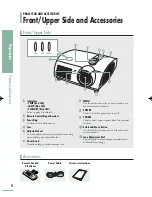
Page 8: ...ng up and down the adjustable feet 6 6 Zoom Knob Used to enlarge or reduce image size 7 7 MENU Use this button to enter or exit a menu or to move forward in a menu 8 8 POWER Used to turn the projector on or off 9 9 SOURCE Used to select input signals from the external sources 1 10 0 Select and Move Button Use this button to move to or select an item within a menu 1 11 1 Lenz Adjustment Dial You ca...

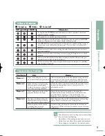
Page 9: ...mal operating condition When temperature inside of the projector becomes too high The lamp is malfunctioning after abnormal power off or restarting right after turning off the projector When brightness of the picture screen degrades or image deterioration is found If the symptom remains even after disconnecting and then reconnecting the power cord and turning the projector on again contact your pr...

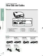
Page 10: ...d to the connection port Component Cable Optional Parts Connected to the connection port PC Video Cable Optional Parts Connected to the connection port Ø DVI D Cable Optional Parts Connected to the connection port ˆ 1 1 Remote Control Signal Receiver 2 2 S VIDEO Input port 3 3 COMPOSITE Input ports 4 4 RS 232C port 5 5 DVI Input port 6 6 PC Input port 7 7 AC Power Input 8 8 Power Switch 9 9 Compon...

Page 11: ... 10 0 MENU Used to display Menu Screen 1 11 1 œ Move Select Used to move to or select each menu item 1 12 2 OFF Used to turn off the projector 1 13 3 LIGHT Page 13 Used to operate remote control in dark room 1 14 4 PC Pages 25 64 66 70 Used to switch to PC Mode 1 15 5 DVI Page 25 64 Used to switch to DVI Mode 1 16 6 COMPOSITE Pages 23 26 Used to switch to COMPOSITE Mode 1 17 7 CUSTOM Page 31 Used ...

Page 12: ...lid to remove it 2 Insert two AAA sized 1 5V batteries by matching 3 Close the lid PROJECTOR AND ACCESSORIES Operating the Remote Control Operating Move Select Button Inserting Batteries into Remote Control Move Menu Item Down Move Menu Item Up Select the current setting Setting the Adjustment left or move to upper item ...

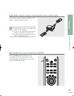
Page 13: ...se new and used batteries together Replace two batteries at the same time Remove batteries when the projector is not used for long periods of time Press the LIGHT button of the remote controller for five seconds The remote control buttons are lit for about 5 seconds and turn off automatically LIGHT Allowable range angle of receiving the remote control signal Using Remote Control in Dark Place LIGH...

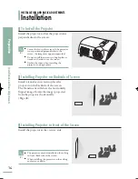
Page 14: ...age projected from the projector horizontally Page 48 Install the projector at the viewers side INSTALLATION AND BASIC ADJUSTMENTS Installation Preparation Installation and Basic Adjustments To Install the Projector Installing Projector on Backside of Screen Installing Projector in Front of the Screen NOTE Center the lens to the screen If the projector is not positioned perpendicular to the screen...

Page 15: ...g the power cord from the wall outlet and do not press the O side of the power switch at the back of the projector during the cooling time approximately one and a half minutes Insufficient cooling may reduce the life time of the product During the cooling time the LAMP operating LED on the main body blinks 4 When the cooling operation is successfully completed the LAMP operating LED on the main bo...

Page 16: ...anipulating the Zoom Knob 2 Focus the picture on the screen using the Focus Ring 1 2 NOTE Focus may appear dim if the projector is installed at a shorter than recommended distance Page 19 Zoom Knob Focus Ring INSTALLATION AND BASIC ADJUSTMENTS Zoom and Focus Adjustment Using the Zoom Knob and the Focus Ring ...

Page 17: ...tor adjust the Adjustable Feet of the projector NOTE You may adjust the level of the projector up to 5 degrees Depending on the position of the projector Keystone distortion of image may appear Page 50 Adjustable Feet INSTALLATION AND BASIC ADJUSTMENTS Leveling with Adjustable Feet ...

Page 18: ...ft Dial Move the picture projected on the screen up and down within the lens range by turning the Lens Shift Dial on the top side of the projector with your fingers UP DOWN INSTALLATION AND BASIC ADJUSTMENTS Using the Lens Shift Dial Using the Lens Shift Dial ...

Page 19: ... 555 3 444 2 422 0 399 8 377 6 355 4 333 2 311 0 288 7 266 5 244 3 222 1 199 9 177 7 155 5 133 3 111 1 95 5 88 8 73 3 67 5 374 6 312 2 249 7 237 2 224 7 212 3 199 8 187 3 174 8 162 3 149 8 137 3 124 9 112 4 99 9 87 4 74 9 62 4 53 7 49 9 41 2 37 9 10 5 8 6 6 9 6 6 6 2 5 9 5 5 5 2 4 8 4 5 4 1 3 8 3 5 3 1 2 8 2 4 2 1 1 7 1 5 1 4 1 1 1 0 13 6 11 4 9 1 8 6 8 2 7 7 7 3 6 8 6 4 5 9 5 5 5 0 4 5 4 1 3 6 3 ...

Page 20: ......

Page 21: ...V I S U A L R E A L I S M Connections and Source Setup Before Connections 22 Connecting to Video Equipment 23 Setting up the External Input Source 26 Naming the External Connections 27 ...

Page 22: ...e to the projector 3 Check the type of ports the projector is connected to 4 This product receives video signals from an external device and displays the video to a screen For audio signals an additional audio system is required Check the following Before Connecting Before Connections Check the followings before connecting the projector to other devices Connections and Source Setup Before Connecti...

Page 23: ...elect Composite Connect the projector and the video equipment via S Video cable and press the S VIDEO button to select S Video When Composite Mode is not available check the video cables are in place 1 Viewing the picture NOTE Check that the projector and the video equipment are turned off before connecting cables This projector does not support sound Separate audio system is needed for sound This...

Page 24: ...onent port at the back of the DVD with the component cable Turn on the projector and press the COMP 1 button to select Component1 Press the COMP 2 button to select Component2 if COMPONENT2 is connected When Component Mode is not available check that the component cables are in place Viewing the picture NOTE Component Ports are marked as Y PB PR Y B Y R Y or Y Cb Cr depending on the manufacturer Co...

Page 25: ...ou can connect a digital broadcast receiver using the DVI or PC input port of the projector 2 Turn on the projector and press the COMP 1 button to select Component1 Press the COMP 2 button to select Component2 if COMPONENT2 is connected If the receiver is connected to DVI or PC port press the DVI or PC button to select DVI or PC respectively When Component Mode is not available check that the comp...

Page 26: ...nal Input Source You can select a device connected to the projector to display Press the button to select Input The Input menu is displayed 2 Press the button to select Source List The Source List menu is displayed 3 Press the or button to move to desired input mode then press the button The source input you chose is displayed If the input mode is not selected check that cables are in place 4 Pres...

Page 27: ... Name then press the button The Edit Name menu is displayed 3 Press the EXIT button to exit the settings 6 Press the or button to move to desired device then press the button Setup is switched to the selected device 5 Press the or button to move to edited input mode then press the button 4 Input Source List Component1 Edit Name Move Enter Return Edit Name Component1 Component2 S Video Composite PC...

Page 28: ...Picture Adjustment ...

Page 29: ...ng the Color Standard 32 Selecting and Adjusting Color Temperature 33 Gamma Correction 34 Saving Custom Picture Settings 35 Setting up DNIe 36 Selecting Picture Size 37 Screen Position Adjustment 39 Selecting Noise Reduction 40 Color Control 41 Film Mode 42 Overscan 43 Setting the Black Level 44 Still Picture 45 ...

Page 30: ...tandard Movie 1 Movie 2 User 1 User 2 User 3 Custom sequentially 4 Press the EXIT button to exit the settings 5 Picture Color Gamma Mode Temperature Dynamic 9300K Graphic Gamma mode that matches a PC screen Standard 8000K Video Gamma mode normal that matches a TV screen Movie1 6500K Film Film mode gamma Movie2 5500K Picture Picture Mode Movie 1 Custom Picture Picture Size Full Position DNIe Off No...

Page 31: ...menu is displayed Refer to number 4 below to make adjustments One Touch 1 MENU 2 3 4 2 3 4 œ 5 EXIT Press the MENU button The main menu is displayed 1 Press the or button to move to Picture Press the button The Picture menu is displayed 2 Press the or button to move to Custom Picture then press the button The Custom Picture menu is displayed 3 Press the or button to move to desired item then press...

Page 32: ...ineers HD High Definition 1125 scan lines standard ATSC definition TV submitted to the ITU R by U S Japan and Canada in 1986 EBU Regulations and standards for European PAL Broadcasting Production and Technology SECAM standardized by the European Broadcasting Union Press the or button to move to Color Standard then press the button The Color Standard options will be displayed 4 Press the œ or butto...

Page 33: ...e quality for black and white films Color temperature of the picture mode of Movie2 is set to 5500K 6500K This temperature is used for the most video productions It is set as Movie1 when it is manufactured and may deliver the most precise tint 8000K The color temperature appropriate to quite bright places and saved in D Picture Mode The sharpness and brightness are emphasized 9300K The color tempe...

Page 34: ...ings 6 Press the or button to move to Gamma then press the button The Gamma is selected 4 Press the or button to move to desired mode then press the button Setup is switched to the selected mode 5 Picture Picture Mode Movie 1 Custom Picture Picture Size Full Position DNIe Off Noise Reduction Off More Move Enter Return Custom Picture More Color Standard SMPTE_C Color Temperature Gamma Film Save Mov...

Page 35: ...ings 7 Press the or button to move to Save then press the button The Save menu is displayed 4 Press the or button to move to desired mode then press the button 5 Press the œ or button to move to OK then press the button Setup is switched to the selected mode 6 Save Move OK Save Current Setting to User1 Picture Picture Mode Movie 1 Custom Picture Picture Size Full Position DNIe Off Noise Reduction ...

Page 36: ...the or button to move to DNIe then press the button The DNle options will be displayed 3 Press the EXIT button to exit the settings 5 Press the or button to move to On then press the button Setup is switched to the selected mode 4 Off DNle Mode Off Demo DNle On Off Picture Comparison Mode On The mode when the DNIe function is enabled DNIe Mode Picture Picture Mode Movie 1 Custom Picture Picture Si...

Page 37: ...icture menu is displayed 2 Press the or button to move to Picture Size then press the button The Picture Size is selected 3 Press the EXIT button to exit the settings 5 Press the or button to move to desired mode then press the button Setup is switched to the selected mode 4 Picture Picture Mode Movie 1 Custom Picture Picture Size Full Position DNIe Off Noise Reduction Off More Move Enter Return P...

Page 38: ... Mode 4 3 Mode 1080i 720p 576p 480p 576i 480i 480i Signal Input Mode O O O O O O O O O O O O O O O O O O O Full X X O O X X X X O O X X X X O O O O O Zoom1 X X X X X X X X X X X X X X X X O O O Zoom2 Picture Size HD HD PC HD SD SD Source DVI PC D Sub Composite S Video O X O O X O O X O O X O O O O O O O O 4 3 PC Component NOTE Refer to page 62 for display modes supported ...

Page 39: ...he button The Position is displayed 3 Press the EXIT button to exit the settings 5 Press the œ or buttons to adjust the position The screen position is determined according to the selected screen position 4 Picture Picture Mode Movie 1 Custom Picture Picture Size Full Position DNIe Off Noise Reduction Off More Move Enter Return Position Move Return œ NOTE The respective position information is set...

Page 40: ... Reduction then press the button The Noise Reduction options will be displayed 3 Press the EXIT button to exit the settings 5 Press the or button to move to On then press the button Noise Reduction is activated If you select Off Noise Reduction is disabled 4 Picture Picture Mode Movie 1 Custom Picture Picture Size Full Position DNIe Off Noise Reduction Off More Move Enter Return Picture Picture Mo...

Page 41: ... move to Color Control then press the button The Color Control options will be displayed 3 Press the EXIT button to exit the settings 5 Press the œ or button to move to desired mode then press the button The picture will only be displayed using the selected color 4 Off Shows the picture in the original color Monochrome Shows the picture in black and white color by filtering out all color signals R...

Page 42: ...s for movies Picture Adjustment Film Mode 42 1 MENU 2 3 4 2 3 4 5 EXIT Press the MENU button The main menu is displayed 1 Press the or button to move to Picture then press the button The Picture menu is displayed 2 Press the or button to move to Film Mode then press the button The Film Mode options will be displayed 3 Press the EXIT button to exit the settings 5 Press the or button to move to On t...

Page 43: ...icture Adjustment Overscan 43 1 MENU 2 3 4 2 3 4 5 EXIT Press the MENU button The main menu is displayed 1 Press the or button to move to Picture then press the button The Picture menu is displayed 2 Press the or button to move to Overscan then press the button The Overscan options will be displayed 3 Press the EXIT button to exit the settings 5 Press the or button to move to On then press the but...

Page 44: ...e then press the button The Picture menu is displayed 2 Press the or button to move to Black Level then press the button The Black Level options will be displayed 3 Press the EXIT button to exit the settings 5 Press the œ or button to move to desired mode then press the button Setup is switched to the selected mode 4 7 5 IRE Sets the light level of the darkest portion of the video signal to high I...

Page 45: ...45 Picture Adjustment Still Picture Still Picture Used to pause playback to see a still picture Press the STILL button Each press of the button pauses and resumes play back One Touch ...

Page 46: ......

Page 47: ...U A L R E A L I S M Setup Flipping Reversal of Projected Image 48 Light Setting 49 Correcting Vertical Keystone 50 Test Patterns 51 Restoring the Factory Default Settings 52 Information 53 Setting the LED 54 ...

Page 48: ...ly Reversed Image Rear Ceiling Horizontal Vertical Reversed Image Install Menu Press the MENU button The main menu is displayed 1 Press the or button to move to Setup The Setup menu is displayed 2 Press the button again Press the or button to move to desired mode then press the button Setup is switched to the selected mode 4 Press the EXIT button to exit the settings 5 Press the button Install is ...

Page 49: ...light level of the lamp you may experience more noise which is produced when the projector is cooled down Light Setting Mode Press the MENU button The main menu is displayed 1 Press the or button to move to Setup then press the button The Setup menu is displayed 2 Press the EXIT button to exit the settings 5 Press the or button to move to Light Setting then press the button The Light Setting optio...

Page 50: ... properly to avoid distortion instead of using the V Keystone feature Press the MENU button The main menu is displayed 1 Press the or button to move to Setup then press the button The Setup menu is displayed 2 Press the EXIT button to exit the settings 4 Press the or button to move to V Keystone then press the button Press the œ or button to adjust A separate adjustment window appears for making t...

Page 51: ...ill be displayed 3 Press the or button to move to desired pattern then press the button The selected pattern is displayed 4 Crosshatch You can check whether the picture is distorted or not Screen Size You can refer to picture format sizes such as 1 33 1 or 1 78 1 Color Standard YoucanviewthedifferencebychangingtheColor StandardtoSMPTE_D HD EBU Formoreinformation abouttheColorStandard refertopage32...

Page 52: ... or button to move to Setup then press the button The Setup menu is displayed 2 Press the EXIT button to exit the settings 5 Press the or button to move to Factory Default then press the button The Factory Default screen will appear 3 Press the œ or button to move to OK then press the button Setting values are returned to factory defaults 4 Setup Install Front Floor Light Setting Theater V Keyston...

Page 53: ...Picture Mode Movie1 Picture Size Full Brightness 50 Contrast 50 Color Temperature 6500K R Gain 50 G Gain 50 B Gain 50 R Offset 0 G Offset 0 B Offset 0 Overscan Off Color Standard EBU Color Control Off DNIe On Install Front Floor Light Setting Theater V Keystone 0 Resolution 1024X768 H Frequency 31KHz V Frequency 70Hz Lamp Time 0 Hour OK Setup More Information LED On Move Enter Return Information I...

Page 54: ...s the button The LED options will be displayed 3 Press the or button to move to On then press the button Setup is switched to the selected mode 4 Setup More Information LED On Move Enter Return Setup More Information LED On Move Enter Return Off This mode disables the operating LED However the light will light up regardless of the LED setting when the power is turned on or off or when the projecto...

Page 55: ...V I S U A L R E A L I S M Menu Option Setting the Language 56 Setting the Menu Position 57 Setting the Menu Translucency 58 Setting the Menu Display Time 59 Selecting the Quick Menu 60 ...

Page 56: ...guage is selected 3 Press the button again Press the or button to move to desired language then press the button Setup is switched to the selected language 4 Press the EXIT button to exit the settings 5 Menu Option Language English Menu Position Menu Translucency Opaque Menu Display Time 120 sec Move Enter Return Menu Option Language English Menu Position Menu Translucency Opaque Menu Display Time...

Page 57: ...utton The Menu Option menu is displayed 2 Press the or button to move to Menu Position then press the button The Menu Position is displayed 3 Press the EXIT button to exit the settings 5 Press the œ or button to move to desired position The menu screen will be displayed in the configured position on the screen 4 Menu Position Move Return œ Menu Option Language English Menu Position Menu Translucen...

Page 58: ...utton to move to Menu Translucency then press the button The Menu Translucency options will be displayed 3 Press the EXIT button to exit the settings 5 Press the or button to move to desired mode then press the button Setup is switched to the selected mode 4 Menu Option Language English Menu Position Menu Translucency Opaque Menu Display Time 120 sec Move Enter Return Menu Option Language English ...

Page 59: ...or button to move to Menu Display Time then press the button The Menu Display Time options will be displayed 3 Press the EXIT button to exit the settings 5 Press the or button to move to desired time then press the button Setup is switched to the selected time 4 Menu Option Language English Menu Position Menu Translucency Opaque Menu Display Time 120 sec Move Enter Return Menu Option Language Engl...

Page 60: ...60 Selecting the Quick Menu Menu Option Selecting the Quick Menu Press the QUICK button The menu you used previously will appear One Touch ...

Page 61: ...nnecting to PC Before Connecting to PC 62 Setting up the PC Environment 63 Connecting to PC 64 Automatic Picture Adjustment 66 Frequency Adjustment 67 Fine Tuning with the Phase Adjustment 68 Zooming the Screen 69 Reset the PC 70 ...

Page 62: ...28 322 35 5 25 175 30 24 31 5 31 5 36 36 40 50 49 5 56 25 57 284 65 75 78 75 108 74 25 74 25 74 25 74 25 27 27 13 5 13 5 O O O O O O O O O O O O O O O O O O O O O O O O O O O O O O O O O O O O O O O O O O O O O X X X X X X X X X X X X X X X X X X X X X X X X X X X X SOY SOY SOY SOY SOY SOY SOY SOY Mode Resolution H x V Total Resolution Frequency KHz Polarity Horizontal Sync Frequency Hz Polarity V...

Page 63: ...utton to close the window and click the OK button of the Display Properties window to close the window The computer might begin restart automatically 6 Shut down the PC and connect to the projector Page 64 1 2 3 4 Setting up the PC Environment NOTE Process might vary depending on the type of computers or Windows versions This appliance supports up to 32 bits per pixel in Color quality when it is u...

Page 64: ...D cable supports digital signals only instead of PC Video cable DVI I cable supports analog signals is not supported Use DVD D cable Sound comes out from PC speakers NOTE This product supports Plug Play No driver installation is needed for Windows XP Rear side of Projector PC 1 PC DVI D Cable PC Video Cable or Rear Connection Using PC Video Cable or DVI Cable When connections are all completed con...

Page 65: ...R Ground Green G Ground Blue B Ground Reserved Ground Sync Ground Data DDC Horizontal Sync Vertical Sync Clock DDC Pin No PC Input 1 2 3 4 5 6 7 8 9 10 11 12 T M D S DATA2 T M D S DATA2 T M D S DATA2 4 Shield T M D S DATA4 T M D S DATA4 Clock DDC Data DDC No Connection T M D S DATA1 T M D S DATA1 T M D S DATA1 3 Shield T M D S DATA3 Pin No Signal 13 14 15 16 17 18 19 20 21 22 23 24 T M D S DATA3 5...

Page 66: ...Press the button The Setup menu is displayed 2 Press the or button to move to PC then press the button The PC menu is displayed 3 Press the EXIT button to exit the settings 5 Press the button Auto Adjustment in progress message is displayed and PC screen is adjusted automatically 4 Auto Adjustment in progress Please Wait Setup Install Front Floor Light Setting Theater V Keystone Test Pattern PC Fa...

Page 67: ...Press the or button to move to Setup then Press the button The Setup menu is displayed 2 Press the or button to move to PC then press the button The PC menu is displayed 3 Press the EXIT button to exit the settings 5 Press the or button to move to Coarse then press the button Press the œ or button to adjust A separate adjustment window appears for making the adjustment 4 PC Auto Adjustment Coarse ...

Page 68: ...d 1 Press the or button to move to Setup then Press the button The Setup menu is displayed 2 Press the or button to move to PC then press the button The PC menu is displayed 3 Press the EXIT button to exit the settings 5 Press the or button to move to Fine then press the button Press the œ or button to adjust A separate adjustment window appears for making the adjustment 4 PC Auto Adjustment Coars...

Page 69: ...en Press the button The Setup menu is displayed 2 Press the or button to move to PC then press the button The PC menu is displayed 3 Press the EXIT button to exit the settings 6 Press the œ or button to move to desired position then press the button to extend as you want The screen can be extended by 1 2 4 or 8 times 5 Press the or button to move to Zoom then press the button 4 x2 Move Zoom Return...

Page 70: ...o move to Setup then Press the button The Setup menu is displayed 2 Press the or button to move to PC then press the button The PC menu is displayed 3 Press the EXIT button to exit the settings 6 Press the œ or button to move to OK then press the button The PC is reset to the time of purchasing 5 Press the or button to move to Reset then press the button 4 PC Auto Adjustment Coarse 1344 Fine 0 Zoo...

Page 71: ...Connecting to PC Reset the PC 71 V I S U A L R E A L I S M Troubleshooting Before Contacting Service Personnel 72 ...

Page 72: ...onnected properly the device is not available Image is distorted or trapezoidal Pages 23 25 Symptoms Troubleshooting Note Be sure that the proper external source is selected Check batteries of the remote control If there is a problem replace them with recommended ones Check the angle and distance between the remote control and the projector Be sure that there is no obstacle between the projector a...

Page 73: ...ents of the Countermeasures against Abnormal Operating LEDs The operating LED is lit up Page 9 Noisy lines may appear for PC mode in case of frequency discrepancy Adjust the vertical frequency of your video card on the advanced display property Lines appear on screen Page 67 Be sure to properly connect the external devices Especially connect the component Y Pb Pr cables matching the color codes Gr...

Page 74: ......

Page 75: ... S M Other Information Storage and Maintenance 76 Purchasing Optional Parts 77 Glossary 78 Structure of Screen Menu 80 Lamp Replacement 83 RS 232C Connection and Control 84 Specifications 86 Remote Control Specifications 87 ...

Page 76: ... use flammable materials such as benzene and thinner Do not use a wet cloth It may result in malfunction Do not clean the lens using a fingertip or a sharp object It may leave scratches Cleaning the Inside of the Projector Contact your dealer or service personnel to clean the inside of the projector Contact your dealer if particles or other objects are stuck inside of the projector ...

Page 77: ...ion Purchasing Optional Parts 77 Optional Parts You can purchase at electronics shops or over the Internet DVI D Cable You can purchase at electronics shops or over the Internet Or you can call your dealer or service center Video Cable S Video Cable Component Cable PC Video Cable 1 5V AAA Batteries ...

Page 78: ...olor temperature implies a colder more blue light Analog Broadcast An existing broadcasting signal transmitted by a broadcasting station in accordance with the NTSC standard ANTENNA IN Port This is the port for connecting a TV aerial using a coaxial cable It is generally used to watch public broadcast programs Overscan Overscan cuts the edge of the picture when there is unnecessary information ima...

Page 79: ...sed for digital signal transmissions DLP Digital Light Processing DLP is a digital display technology using a DMD panel developed by TI Texas Instruments of the United States DLP HD2 DC3 This is a grade of DMD panel DMD Digital Micromirror Device A DMD panel is an implementation of DLP technology It consists of microscopic mirrors where each mirror represents a pixel RS 232C Port Service Input Por...

Page 80: ...V Receiver DVD Receiver Game Camcorder Combo PC Input Buttons used for Screen Menu Select an item change setting value Select Composite S Video Component Input Mode Custom Picture Contrast 0 100 Brightness 0 100 Sharpness 0 100 Color 0 100 Tint 0 100 Not supported in 480p mode or above Color Standard SMPTE_C HD EBU Color Temperature 5500K 6500K 8000K 9300K Gamma Film Video Graphic Save User1 User2...

Page 81: ...en Menu 81 Setup Install Front Floor Front Ceiling Rear Floor Rear Ceiling Light Setting Theater Bright V Keystone 50 50 Test Pattern Crosshatch Screen Size Color Standard Red Green Blue White 6500K_White PC Auto Adjustment Coarse Fine Zoom Reset OK Cancel Factory Default OK Cancel Information LED OK Cancel Setup Install Front Floor Light Setting Theater V Keystone Test Pattern PC Factory Default ...

Page 82: ...on Menu Translucency Opaque High Medium Low Menu Display Time 5 10 30 60 90 120 Stay On Other Information Structure of Screen Menu 82 Structure of Screen Menu Continued Menu Option Menu Option Language English Menu Position Menu Translucency Opaque Menu Display Time 120 Sec Move Enter Return ...

Page 83: ...P47 00010A Check that the power cord is unplugged before replacing lamps Even after the power cord has been disconnected the lamp will be hot Allow it to cool down for at least 1 hour before changing the lamp The projector lamp is installed at the bottom of the projector Before you turn the projector over to change the lamp cover the projector with a soft cloth on a flat surface Do not leave the o...

Page 84: ...the INFORMATION command to display the current information on the Projector s screen All the control commands apply to the input source and the Projector s status currently displayed Communication Format Complies with the RS232C Standard Transmission Speed 115 200 bps Parity Bit No Data Length 8 data bits 1 stop bit Argument 1 Argument 2 Argument N Command Response Transmission Sequence and Data F...

Page 85: ...9 4 Position UP 75 2 13 0 DOWN 75 2 13 1 LEFT 75 2 13 2 RIGHT 75 2 13 3 DNIe On 76 0 1 1 Off 76 0 1 0 Demo 76 0 1 2 Noise Reduction On 76 0 8 1 Off 76 0 8 0 CONTROL ITEMS COMMAND PARAMETERS RETURN Black Level 7 5 IRE 76 0 7 0 0 IRE 76 0 7 1 Color Control OFF 76 3 7 0 Monochrome 76 3 7 1 Red 76 3 7 2 Green 76 3 7 3 Blue 76 3 7 4 Film Mode On 75 2 11 1 Off 75 2 11 0 Overscan On 75 2 12 1 Off 75 2 12...

Page 86: ...1080i 3 Frequency Refer to page 67 1 Connector Type 15Pin D Sub 2 Frequency Refer to page 67 1 Signal Type Y Pb Pr 2 Available Format 480i 480p 576i 576p 720p 1080i 3 Frequency Refer to page 67 Signal Format NTSC PAL SECAM Service Port Operating Temperature 32 104ºF 0 40ºC Humidity 10 80 Storage Temperature 4 113ºF 20 45ºC Humidity 5 95 Class B Min 28dB Theater Mode Model Classification SP H800 Pa...

Page 87: ...P SIZE P MODE Button Front Floor Front Ceiling Rear Floor Rear Ceiling CUSTOM STILL V KEYSTONE INSTALL MENU QUICK INFO EXIT Up Down Left Right Enter Data Code 99 98 86 88 84 85 69 8A E4 53 E1 E3 BD E8 E9 EA EB EC ED BC System Code 07 07 07 07 07 07 07 07 07 07 07 07 07 07 07 07 Data Code 1E 42 81 BB EE EF BF 1A 58 1F 2D 60 61 65 62 68 Function and Transmission Codes LEADER PULSE System Code System...

Reviews: