background image

Summary of Contents for SPC-3120
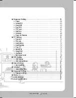
Page 1: ......

Page 2: ...g Techwin makes the best to verify the integrity and correctness of the contents in this document but no formal guarantee shall be provided Use of this document and the subsequent results shall be entirely on the user s own responsibility Samsung Techwin reserves the right to change the contents of this document without prior notice Warranty If the product does not operate properly in normal condi...

Page 3: ...rmful interference when the equipment is operated in a commercial environment This equipment generates uses and can radiate radio frequency energy and if not installed and used in accordance with the instruction manual may cause harmful interference to radio communications Operation of this equipment in a residential area is likely to cause harmful interference in which case the user will be requi...

Page 4: ...ÄÄÄÄÄÄÄÄÄÄÄÄÄÄÄÄÄÄÄÄÄ 30 ÿSCP 3120 On Ceiling Mount Type Installation Example ÄÄÄÄ 31 ÿSCP 3120 Flush Mount Type Installation Example ÄÄÄÄÄÄÄ 34 ÿ SCP 3120V Ceiling Mount ÄÄÄÄÄÄÄÄÄÄÄÄÄÄÄÄÄ 37 ÿ SCP 3120V Mount onto the optimal adaptor ÄÄÄÄÄÄÄÄ 39 ÿ SCP 3120VH ÄÄÄÄÄÄÄÄÄÄÄÄÄÄÄÄÄÄÄÄÄÄÄÄ 40 Interface Symbols ÄÄÄÄÄÄÄÄÄÄÄÄÄÄÄÄÄÄÄÄÄÄÄÄ 42 ÿOperating Your Camera ÄÄÄÄÄÄÄÄÄÄÄÄÄÄÄÄÄÄÄÄ 43 ÿOSD Commands Funct...

Page 5: ...rea MaskingÄÄÄÄÄÄÄÄÄÄÄÄÄÄÄÄÄÄÄÄÄÄÄÄÄÄÄÄÄÄÄÄÄ 73 Ķ Prop P T ÄÄÄÄÄÄÄÄÄÄÄÄÄÄÄÄÄÄÄÄÄÄÄÄÄÄÄÄÄÄÄÄÄÄÄ 74 Ķ Digital Flip ÄÄÄÄÄÄÄÄÄÄÄÄÄÄÄÄÄÄÄÄÄÄÄÄÄÄÄÄÄÄÄÄÄÄ 75 Ķ Image Hold ÄÄÄÄÄÄÄÄÄÄÄÄÄÄÄÄÄÄÄÄÄÄÄÄÄÄÄÄÄÄÄÄÄÄ 76 Ķ Jog Speed ÄÄÄÄÄÄÄÄÄÄÄÄÄÄÄÄÄÄÄÄÄÄÄÄÄÄÄÄÄÄÄÄÄÄ 77 Ķ Max Speed Level ÄÄÄÄÄÄÄÄÄÄÄÄÄÄÄÄÄÄÄÄÄÄÄÄÄÄÄÄÄÄÄ 78 ÿOSD Setting ÄÄÄÄÄÄÄÄÄÄÄÄÄÄÄÄÄÄÄÄÄÄÄÄÄ 79 Ķ OSD Setting ÄÄÄÄÄÄÄÄÄÄÄÄÄÄÄÄÄÄÄÄÄÄÄÄÄÄÄÄÄÄÄÄÄÄ 79 Ķ...

Page 6: ...s useful to monitor moving objects or people passing directly under the camera When an object or a person passes directly under the camera its tilt motor follows the object or person over 100 degrees to the other side of the tilt area without panning The screen inversion starts to occur at 100 degrees or higher is digitally adjusted Multiple Preset Function Saving Up to 12 camera image properities...

Page 7: ... product accordingly For product inquiries please contact the retail shop where you bought the camera The use of equipment such as anaerialladderwhileprovidingafter salesserviceshallbeatyourexpense Unplugthepowerplugduringathunderstormtopreventfireanddamagetotheproduct Thisproductissupportequipmentforasecuritysystem Therefore wecan tcompensateformateriallossesand or personalinjuriesbyrobbery fire ...

Page 8: ...ibrations Donotinstallinhighhumidityorinaplace thatmaybeexposedtooilorgas This installation should be made by a qualified service person Installing this product on your own may result in fire or electric shock For the installation service contact the retail shop where you bought the product May cause product malfunctions electric shocks and fire May cause electric shock May cause fire and damage t...

Page 9: ...aphics quality and product malfunction When using in high temperature conditions provide good ventilation Severe lighting changes or flickering may hinder normal camera operation Do not install under extreme temperature conditions Do not drop the camera or subject it to physical shock Never keep the camera facing direct sunlight or any other strong lights Do not install under unstable lighting con...

Page 10: ...hat are exposed to radioactivity X rays strong electric waves and electro magnetic waves Places that are exposed to outdoor air contaminants e g Dust and car exhaust Places in high humidity Places that are exposed to corrosive gas Smeared and dusty dome covers decrease the picture and video quality Clean the dome cover and camera lens on a regular basis Remove the plastic wrap on the dome cover on...

Page 11: ...SPEED DOME CAMERA User Guide 11 Components and Accessories SCP 3120 8Pin Terminal Block 7Pin Terminal Block User Guide Screw M4x20 4EA Templet BNC Cable Mount Bracket Body ...

Page 12: ...SPEED DOME CAMERA User Guide 12 Body SCP 3120V Components and Accessories 8Pin Terminal Block 7Pin Terminal Block User Guide Screws Plastic Anchor Wrench BNC Cable ...

Page 13: ...SPEED DOME CAMERA User Guide 13 Body SCP 3120VH 8Pin Terminal Block 7Pin Terminal Block User Guide Wrench BNC Cable ...

Page 14: ...ing Mount ÂUsed to Mount the Camera SCP 3120VH onto the ceiling Ceiling Mount ÂUsed to Mount the Camera SCP 3120 3120V onto the wall Hanging Mount Wall Mount ÂUsed to Mount the Camera SCP 3120VH onto the wall Wall Mount ÂUsed to Mount the Wall Mount onto a cylindrical pillar Pole Mount ÂUsed to Mount the Wall Mount onto a corner of the wall Corner Mount ö For SCP 3120 3120V above products are avai...

Page 15: ... 15 Component Names and Functions Side Bottom Screw Hole Communication Setup Switch ID Setup Switch Video Communication Power Alarm Front For the DIP switch settings please refer to the Installing Your Camera on Page 19 Notes 4 1 ...

Page 16: ...SPEED DOME CAMERA User Guide 16 Component Names and Functions Side Bottom Communication Setup Switch ID Setup Switch Video Communication Power Alarm Front 4 1 7 ...

Page 17: ...SPEED DOME CAMERA User Guide 17 4 1 7 Side Bottom Communication Setup Switch ID Setup Switch Video Communication Power Alarm Front ...

Page 18: ...ra 485 485 R RX R RX Controller or DVR Control Signal Connection Power Video Communication Signal Connection The provided BNC cable s blue line is Video Output while the black line is the Ground Power supply adaptor AC has no polarities Controller Auxiliary Signal Connection Alarm Video Controller Power Supply No Name Usage 1 VIDEO Video Output 2 GND Ground 3 485 Controller Data Line 4 485 Control...

Page 19: ...1 Detach the camera frame from the install base and place the bottom of the frame toward you as shown in the picture below 2 Set the switches according to your installation environment For more detailed setup information please refer to the chart on the next page 3 The camera may malfunction if the switches are not fully turned On Off please double check the switches before finishing setup Communi...

Page 20: ...FF OFF ON 11 BOSCH ON OFF ON OFF 12 Resetved ON OFF ON ON 13 Resetved ON ON OFF OFF 14 Resetved ON ON OFF ON 15 Resetved ON ON ON OFF 16 Resetved ON ON ON ON Select a communication protocol for the camera SW2 Pin No Purpose 1 4 Protocol Settings 5 6 Baud Rate Settings 7 Response Mode Settings 8 Termination Settings Installing Your Camera No Baud Rate BPS SW2 5 SW2 6 1 2 400 ON ON 2 4 800 ON OFF 3 ...

Page 21: ...Notes To set up camera IDs refer to the Camera ID Chart next Camera ID DIP Switch Settings SW1 This model is provided with factory defaults of all DIP switches set to OFF The default settings are shaded in the table AD Protocol VICON Protocol GE Protocol Entering Camera OSD 3 Auxilary ON IRIS OPEN IRIS OPEN Exiting Camera OSD 3 Auxilary OFF IRIS CLOSE IRIS CLOSE ENTER IRIS OPEN IRIS OPEN IRIS OPEN...

Page 22: ...FF OFF ON OFF OFF OFF 17 ON OFF OFF OFF ON OFF OFF OFF 18 OFF ON OFF OFF ON OFF OFF OFF 19 ON ON OFF OFF ON OFF OFF OFF 20 OFF OFF ON OFF ON OFF OFF OFF 21 ON OFF ON OFF ON OFF OFF OFF 22 OFF ON ON OFF ON OFF OFF OFF 23 ON ON ON OFF ON OFF OFF OFF 24 OFF OFF OFF ON ON OFF OFF OFF 25 ON OFF OFF ON ON OFF OFF OFF 26 OFF ON OFF ON ON OFF OFF OFF 27 ON ON OFF ON ON OFF OFF OFF 28 OFF OFF ON ON ON OFF ...

Page 23: ... ON ON OFF ON ON ON OFF OFF 60 OFF OFF ON ON ON ON OFF OFF 61 ON OFF ON ON ON ON OFF OFF 62 OFF ON ON ON ON ON OFF OFF 63 ON ON ON ON ON ON OFF OFF 64 OFF OFF OFF OFF OFF OFF ON OFF 65 ON OFF OFF OFF OFF OFF ON OFF 66 OFF ON OFF OFF OFF OFF ON OFF 67 ON ON OFF OFF OFF OFF ON OFF 68 OFF OFF ON OFF OFF OFF ON OFF 69 ON OFF ON OFF OFF OFF ON OFF 70 OFF ON ON OFF OFF OFF ON OFF 71 ON ON ON OFF OFF OFF...

Page 24: ...FF ON ON OFF 102 OFF ON ON OFF OFF ON ON OFF 103 ON ON ON OFF OFF ON ON OFF 104 OFF OFF OFF ON OFF ON ON OFF 105 ON OFF OFF ON OFF ON ON OFF 106 OFF ON OFF ON OFF ON ON OFF 107 ON ON OFF ON OFF ON ON OFF 108 OFF OFF ON ON OFF ON ON OFF 109 ON OFF ON ON OFF ON ON OFF 110 OFF ON ON ON OFF ON ON OFF 111 ON ON ON ON OFF ON ON OFF 112 OFF OFF OFF OFF ON ON ON OFF 113 ON OFF OFF OFF ON ON ON OFF 114 OFF...

Page 25: ...FF ON 145 ON OFF OFF OFF ON OFF OFF ON 146 OFF ON OFF OFF ON OFF OFF ON 147 ON ON OFF OFF ON OFF OFF ON 148 OFF OFF ON OFF ON OFF OFF ON 149 ON OFF ON OFF ON OFF OFF ON 150 OFF ON ON OFF ON OFF OFF ON 151 ON ON ON OFF ON OFF OFF ON 152 OFF OFF OFF ON ON OFF OFF ON 153 ON OFF OFF ON ON OFF OFF ON 154 OFF ON OFF ON ON OFF OFF ON 155 ON ON OFF ON ON OFF OFF ON 156 OFF OFF ON ON ON OFF OFF ON 157 ON O...

Page 26: ... OFF ON 188 OFF OFF ON ON ON ON OFF ON 189 ON OFF ON ON ON ON OFF ON 190 OFF ON ON ON ON ON OFF ON 191 ON ON ON ON ON ON OFF ON 192 OFF OFF OFF OFF OFF OFF ON ON 193 ON OFF OFF OFF OFF OFF ON ON 194 OFF ON OFF OFF OFF OFF ON ON 195 ON ON OFF OFF OFF OFF ON ON 196 OFF OFF ON OFF OFF OFF ON ON 197 ON OFF ON OFF OFF OFF ON ON 198 OFF ON ON OFF OFF OFF ON ON 199 ON ON ON OFF OFF OFF ON ON 200 OFF OFF ...

Page 27: ...0 OFF ON ON OFF OFF ON ON ON 231 ON ON ON OFF OFF ON ON ON 232 OFF OFF OFF ON OFF ON ON ON 233 ON OFF OFF ON OFF ON ON ON 234 OFF ON OFF ON OFF ON ON ON 235 ON ON OFF ON OFF ON ON ON 236 OFF OFF ON ON OFF ON ON ON 237 ON OFF ON ON OFF ON ON ON 238 OFF ON ON ON OFF ON ON ON 239 ON ON ON ON OFF ON ON ON 240 OFF OFF OFF OFF ON ON ON ON 241 ON OFF OFF OFF ON ON ON ON 242 OFF ON OFF OFF ON ON ON ON 243...

Page 28: ...ximum please use an auxiliary video amp Communications Cable For the camera to communicate with the controller a RS 485 communications line is required To ensure the quality of long distance communication and the accuracy of the overall communication it is recommended using a twisted pair cable such as UTP Caution Depending on the camera s environment the communications distance may vary Power Ada...

Page 29: ...C MENU PRES ET GROU P TRAC K CAM 1 2 3 4 5 6 7 8 9 0 MON CLOS E OPEN NEAR FAR WIDE TELE PTZ DVR MTX SETUP ESC FUNC ENTER MENU SEAR CH MULT I REC MENU PRES ET GROU P TRAC K CAM 1 2 3 4 5 6 7 8 9 0 MON CLOS E OPEN NEAR FAR WIDE TELE PTZ DVR MTX SETUP ESC FUNC ENTER 1 2 16 1 2 16 1 2 16 1 2 16 Coaxial Communication Coaxial Communication CONTROLLER SUB CONTROLLER MAIN CONTROL LINE VIDEO LINE CONTROL V...

Page 30: ...ctures below show the front view of the camera installed with a wall or flush bracket For more instructions on installing the camera please refer to the following guidelines Wall Mount Type Installation Flush Mount Type Installation Installation Examples Ceiling ...

Page 31: ...Mount Type Installation Example 1 Attach Template Attach the template on the ceiling facing the Front mark to the main monitoring direction Drill a hole in the ceiling according to the 60 mm diameter hole marked on the template and then drop the camera cables down through the hole 2 Mount Bracket Using the 4 screws install the mount brackets on the ceiling matching its directional guides with thos...

Page 32: ...t bracket and the arrow shows a match to match Insert the mount bracket to the matching holes in the camera and then turn the camera clockwise 4 Secure the Camera Match the screw holes in the camera and mount bracket and then fasten with the screw Alingn The Arrow Alingn The Arrow Alingn The Arrow Alingn The Arrow Screw Hole Mount Bracket ...

Page 33: ...roper terminals on the bottom of the camera For more detailed instructions please refer to Page 18 Camera Wiring Interface Board 6 Camera DIP Switch Setup DIP switches for communication and ID setup are located on the bottom of the camera For more instructions please refer to Page 20 ...

Page 34: ...n the Ceiling Attach the template and then drill a hole according to the 120 mm diameter hole marked on the template Drop down the camera cables through the hole Drill another small hole for a screw to secure the camera 2 Exiting Camera OSD Rotate the dome cover counterclockwise to detach it from the camera ...

Page 35: ...o the proper terminals on the bottom of the camera Refer to Page 18 Camera Wiring Interface Board Configure the DIP switches on the bottom of the camera for communication and ID Refer to Page 20 3 Detach the Mount Housing Remove the 3 screws and then detach the mount housing from the camera ...

Page 36: ...mera Fit the camera to the hole on the ceiling and then secure the camera using 3 Product enclosed Fixture Screws M4x20 6 Assemble Dome Cover Assemble Dome Cover Insert the grooves on the dome cover into ones on the camera and then turn clockwise to fasten Screw Screw Ceiling Ceiling ...

Page 37: ...les 5 mm in diameter and at least 35 mm in depth for each for the screws x4 to be inserted in the bottom of the surface mount and insert the provided plastic anchor HUD5 to the end Insert the cables into the cable hole and fix the SCREW TAPPING TH M4xL30 to the plastic anchor that was inserted in the hole for fixing the surface mount x4 surface body screw SURFACE MOUNT ...

Page 38: ...range the cables inside the surface mount so that they should not be entangled or stuck in and align the guide rib of the camera with that of the surface mount Use the L shaped wrench to tighten the screws x4 so that the camera is secured to the mount To ensure waterproofness take caution lest that the outer gasket should get loose or be stuck in SAFETY WIRE SURFACE MOUNT SCREW MAIN FRAME GASKET G...

Page 39: ...low step 1 in Ceiling Mount above and remove the surface mount 2 Insert the cables into the cable hole on the surface mount and fix them to SBP 300HM HANGING MOUNT using SCREW MACHINE BH M4xL10 x4 3 Repeat step 3 through step 4 in Ceiling Mount above to complete the installation ...

Page 40: ...ll help removing the housing 2 Fix the housing to the NP 1 5 tapped pipe wall mount SBP 300WM or ceiling mount SBP 300CM by turning it clockwise For waterproofness and lock between the two component parts use the Teflon tape to wrap them around PIPE or MOUNT PIPE or MOUNT HOUSING HOUSING NP 1 5 TAP HOUSING MAIN FRAME SCREW SCREW 4 1 7 ...

Page 41: ...Interface Board section in this manual 4 Arrange the cables inside the housing lest they be damaged or stuck in and use the L shaped wrench to tighten 4 screws to the housing To ensure waterproofness this step needs your special care Otherwise the gasket on the outer side of the product may be loose or just stuck in SAFETY WIRE GASKET HOUSING MAIN FRAME SCREW SAFETY WIRE ...

Page 42: ... Alarm Input Port Status Display in the upper right of the screen blink Current Alarm Port Display According to Input Alarm Ports Priority Only one of in the upper right of the screen blinks Preset Number Display Settings If a preset number is already available H If a preset location is the camera s home position If an OSD Menu has Sub Menus displays at the end of the menu If an OSD Menu Does Not ...

Page 43: ...e joystick of the controller or its direction buttons Controlling Zoom Move the joystick clockwise Tele or counterclockwise Wide or use the zoom buttons Accessing Screen Menus Press the Menu or OSD button on the controller This dome camera can be operated using two methods Using hot keys on its dedicated controller or accessing the OSD On Screen Display on the video output The OSD menu commands ar...

Page 44: ...utter OFF A FLK MANUAL Shutter Speed Sens Up OFF Auto Sens up Limit 2X 4X 512X Back Light OFF WDR Limit LOW MEDIUM HIGH Level 1 18 BLC Up Down Left Right Increase Decrease AGC OFF LOW MEDIUM HIGH MANUAL AGC Level 1 16 DNR OFF LOW MEDIUM HIGH XDR OFF LOW MEDIUM HIGH Day Night Mode Auto Color BW Burst ON OFF Dwell Time 2 3 5 10 15 20 25 30 SEC Others Sync INTERNAL LINE LOCK Line Lock Phase 0 359 Sha...

Page 45: ...g Mode PAN TILT P T PRESET Preset No 1 128 HOME Time 5 30 SEC 1 5 MIN Power On Resume ON OFF Sequence Setting Preset Edit Motion Det Motion OFF DETECTION TRACKING Advanced OFF FIXED MOVED Display OFF ON Sensitivity 1 7 Resolution 1 5 The rest of the installation steps are the same as in the camera setting section P T Setting Pan Limit Position Activation ON OFF Tilt Limit Position Activation ON OF...

Page 46: ...ay ON OFF Date Format Set Date Time Format Set Time Calibration SEC DAY Alarm Setting Alarm Enable ON OFF Alarm Input In1 MOD NC NO OFF P 1 2 SEQ OFF HOME PRESET SWING GROUP TOUR TRACE A PAN In2 Alarm Output Setting 1 2 1 2 MD AUX Timer 1 2 OFF MOMENTARY ON 1 60 Sec 1 60 Min Out Off 1 2 MD Dwell Time OFF ON 1 60 Sec 1 60 Min Initialize Power On Reset Cancel Execute Factory Default Set Cancel Execu...

Page 47: ...e normally under the following conditions When background illumination is low While Slow Shutter is in operation If the zoom level is set too high When background illumination is too high If a long distance object and a close distance object appear together within a monitoring area If there is no contrast e g Ceiling or a wall If the camera is facing a thin horizontal line Auto Focus focuses on an...

Page 48: ...ghting conditions changes MANUAL Enables customization of the Red and Blue gains 2 White Balance Ķ Main Menu Camera Setting White Balance White Balance may not work properly under the following conditions When the color temperature of the environment surrounding the subject is out of the control range When the ambient illumination of the subject is dim If the camera is directed towards a fluoresce...

Page 49: ...picture flickering Flickering can happen when artificial lighting frequencies clash with camera frame rates MANUAL Enables manual adjustment of the shutter speed Sens Up AUTO Automatically detects light levels and maintains a clear picture at night or under low light conditions SENS UP LIMIT Adjusts to the maximum powered zoom per frame While the Internal Sync mode is in effect setting the shutter...

Page 50: ...nu Camera Setting Back Light Unlike other cameras Samsung Techwin s unique A1 DSP chip gives you a clear image of the subject even with bright backlight Back Light Mode OFF Disables the Backlight mode WDR Activates the Wide Dynamic Range mode BLC Activates a user defined backlight compensation mode ª Main Menu Camera Setting Sequence Setting P T Setting OSD Setting Alarm Setting Initialize Passwor...

Page 51: ...WDR operation noise discoloration spots and whitish symptoms may occur depending on lighting conditions If they occur stop using WDR Notes Limit Three WDR sensitivity levels are available in 3 Low Medium and High Note that the higher the sensitivity level the lower the contrast in the light and dark areas becomes Level Adjusts the screen brightness in WDR mode 4 2 WDR Ķ Main Menu Camera Setting Ba...

Page 52: ... location and size of a selected area Zoom Control Zoom Tele Enlarges the size of a selected area Zoom Wide Reduces the size of a selected area BLC Ć Upć Down ą Left Ą Right W Decrease T Increase Camera Setting Zoom Focus White Balance ATW IN Exposure Back Light BLC AGC DNR MEDIUM XDR OFF Day Night Others ª Main Menu Camera Setting Sequence Setting P T Setting OSD Setting Alarm Setting Initialize ...

Page 53: ...tness if the camera has captured an object under low light conditions The OFF LOW MEDIUM HIGH and MANUAL modes are available Camera Setting Zoom Focus White Balance ATW IN Exposure Back Light OFF AGC DNR MEDIUM XDR OFF Day Night Others ª Main Menu Camera Setting Sequence Setting P T Setting OSD Setting Alarm Setting Initialize Password Setting Status ...

Page 54: ...nt of noise but generates almost no afterimage MEDIUM The most commonly used mode Reduces a suitable amount of noise while generating a subtle afterimage HIGH Reduces noise significantly but generates obvious afterimages Camera Setting Zoom Focus White Balance ATW IN Exposure Back Light OFF AGC DNR MEDIUM XDR OFF Day Night Others ª Main Menu Camera Setting Sequence Setting P T Setting OSD Setting ...

Page 55: ...s to even out the overall brightness of the image with high contrast between bright and dark spots The OFF LOW MEDIUM and HIGH modes are available XDR OFF XDR ON Camera Setting Zoom Focus White Balance ATW IN Exposure Back Light OFF AGC DNR MEDIUM XDR OFF Day Night Others ª Main Menu Camera Setting Sequence Setting P T Setting OSD Setting Alarm Setting Initialize Password Setting Status ...

Page 56: ...B W mode at all times By using the Burst On Off sub menu burst signals can be retained or disabled Dwell Time The duration of both the lighting conditions can be customized to let the camera delay the switching between the daytime and night time settings If the camera is in B W mode and connected to equipment that requires external sync through burst signals set the Burst On Off option to On Day N...

Page 57: ...aused by due to the wind and other reasonable causes VPS This function enhances the outline of moving subject which improves the sharpness of a captured image as fine as a still image ª Others Sync INTERNAL Sharpness 2 Freeze OFF Stabilizer OFF VPS OFF Camera Setting Zoom Focus White Balance ATW IN Exposure Back Light OFF AGC DNR MEDIUM XDR OFF Day Night Others ª Main Menu Camera Setting Sequence ...

Page 58: ...e Enter key redirects the menu to the screen shown below Using the joystick adjust the location of the Pan and Tilt functions and then set the Zoom and Focus command In Preset Settings the Zoom and Focus command is controllable only by the Zoom command To switch between Zoom and Focus use the Preset 1 and 2 commands as shown below Preset Setting 1 PST ZOOM 2 PST FOCUS Sequence Setting Preset Swing...

Page 59: ... Night Refer to the section entitled Setting Up Your Camera Motion Det Refer to the 10 3 Motion Detection Scene Adj Enables setting the Shutter AGC DNR XDR Sens Up White Balance Stabilizer and for more information about interface terminology please refer to the section entitled Setting Up Your Camera 10 2 Preset Edit Ķ Main Menu Sequence Setting Preset Edit Sequence Setting Preset Swing SEQ Group ...

Page 60: ...sensitivity of motion sensor Resolution The bigger the resolution setting the smaller the object that can be detected Motion Det Motion OFF Advanced Display Sensitivity 1 Resolution 1 If you set it to DETECTION the FIXED MOVED option of ADVANCED menu will not be available In following situations motion detection and tracking function may not work properly When there is sudden changes of brightness...

Page 61: ...ystick and the Enter key to perform the Set command and save the name OSD Setting Camera ID ON Camera Name Preset Number ON Preset Name ª Preset Name ON OFF OFF Edit ª ª ª Preset Edit Preset 001 1 255 Main Menu Camera Setting Sequence Setting P T Setting OSD Setting Alarm Setting Initialize Password Setting Status PSET Name ABCDEFGHIJKLM NOPQRSTUVWXYZ abcdefghijklm nopqrstuvwxyz 1234567890 BACK SP...

Page 62: ...þþþ þþþþþ ª ª ª 10 5 Preset Execution Deletion Memory Check Ķ Main Menu Sequence Setting Preset Home Position Sets one of the currently configured preset positions as the home position Execute Recalls a saved preset location Clear Deletes the selected preset location Status Opens a map of saved preset locations An area saved as a preset location is displayed with the icon Preset Setting Edit Home ...

Page 63: ...he Pan and Tilt functions for the Swing operation Swing Settings Execute Clear Settings Each of the Swing menus have sub menus with the settings Select 2 preset locations by using the joystick Speed indicates the camera s movement speed DWT indicates the camera s duration of stay at a preset location Execute Executes the Swing operation Clear Deletes data in the Swing memory Swing SEQ Pan Swing Ti...

Page 64: ... desired preset numbers into the PSET section DWT indicates the camera s duration of stay at a preset location SPD shows the camera s movement speed by 64 different levels Execute Executes the group operation Clear Deletes the selected group Group SEQ 1 NO PSET DWT s SPD 001 003 64 002 003 64 003 003 64 004 003 64 005 003 64 006 003 64 007 003 64 ª Sequence Setting Preset Swing SEQ Group SEQ Tour ...

Page 65: ...ng screen Using the joystick you can enter desired group numbers to the Group section DWT indicates the camera s standby time before a new group is recalled Execute Executes the group operation Clear Deletes the selected group Tour SEQ NO Group DWT s 01 003 02 003 03 003 04 003 05 003 06 003 ª Sequence Setting Preset Swing SEQ Group SEQ Tour SEQ PTZ Trace Auto Run Power On Resume ON Main Menu Came...

Page 66: ...ion As a trace is saved the remaining capacity of the memory card is displayed When the memory card is full it turns off with a message Mem Left 000 on the screen Use the OSD On button to pause while saving a trace When using the SCC 3100A SCC 1000 controller When Using Different Protocols Clear Deletes a saved Trace route ª Sequence Setting Preset Swing SEQ Group SEQ Tour SEQ PTZ Trace Auto Run P...

Page 67: ...ected Group mode TOUR Auto run a selected Tour mode TRACE Auto run a selected trace mode A PAN Auto run a 360 degree pan To activate the panning command you need to set up the camera s tilt angle and auto pan speed manually SCHEDULE Schedule a sequencing action by day and time Refer to the next page Time Enables setting up an Auto Run duration The duration can be 5 30 seconds or 1 5 minutes ª Sequ...

Page 68: ...ct the beginning time and sequencing action to schedule the action 16 Schedule Schedule enables you to schedule a sequencing action by day and time Schedule Set No START SEQ No 1 09 00 HOME 2 00 00 OFF 3 00 00 OFF 4 00 00 OFF 5 00 00 OFF 6 00 00 OFF Clear ª ª Auto mode is disabled when AGC is turned OFF This function is only available when Color or B W mode is selected The camera time must be setu...

Page 69: ...mes the action when the power is reconnected ª Sequence Setting Preset Swing SEQ Group SEQ Tour SEQ PTZ Trace Auto Run Power On Resume ON Power On Resume cannot resume a sequence action if the camera s internal battery is completely discharged after the camera was left without power supply for a long time The data of the sequence action however remains safe even if the internal battery is complete...

Page 70: ...t to select a movement range from the starting point to the end ON OFF Cancels or activates the Pan Tilt Limit functions The following picture shows the Tilt Limit setting Move the joystick left and right to select a movement range from the starting point to the end P T Setting ª P T Setting Pan Limit Tilt Limit Area Setting Area Masking Prop P T ON Digital Flip ON Image Hold OFF Jog Speed MANUAL ...

Page 71: ...t range of the Tilt operation Position Selecting the Position menu brings up the following screen if it is for the Tilt Limit setting Move the joystick left and right to select a movement range from the starting point to the end END LIMIT Enter Set ESC Exit p START LIMIT Enter Set ESC Exit ON OFF Enables or disables Tilt Limit ª P T Setting Pan Limit Tilt Limit Area Setting Area Masking Prop P T O...

Page 72: ... use the joystick and the Enter key to perform the Set command and save the name Position As shown in the picture below move the joystick to select the upper left corner and lower right corner of an area On Off Cancels or activates the display function of selected areas ª ª Area 1 Area Name Position Activation OFF Area Setting Area 1 Area 2 Area 3 Area setting Enter Set ESC Exit ª P T Setting Pan ...

Page 73: ...For the new mask setup you can set the camera position by using pan tilt and zoom functions Style You can set the four kinds mosaic Area Masking Activation OFF Edit For better privacy protection make your privacy zone bigger than the required bigger by about 30 Video portion of mosaic pattern or colored by the privacy zone setup is not recoverable Notes ª ª P T Setting Pan Limit Tilt Limit Area Se...

Page 74: ... and counterclockwise Wide accelerates the Pan and Tilt speed allowing detailed adjustments Turning this Off executes the function the optical 1x zoom speed regardless of how far the lens is zoomed in ª P T Setting Pan Limit Tilt Limit Area Setting Area Masking Prop P T ON Digital Flip ON Image Hold OFF Jog Speed MANUAL Max Speed Level 5 Main Menu Camera Setting Sequence Setting P T Setting OSD Se...

Page 75: ...amera tilt monitor follows the object or person over 100 degrees to the other side of the tilt area without panning The screen inversion occurs at 100 degrees or higher and is digitally adjusted ª P T Setting Pan Limit Tilt Limit Area Setting Area Masking Prop P T ON Digital Flip ON Image Hold OFF Jog Speed MANUAL Max Speed Level 5 Main Menu Camera Setting Sequence Setting P T Setting OSD Setting ...

Page 76: ...l the camera reached the next location This is useful to help the screen observer keep sharp eyes and to monitor multiple locations within a network ª P T Setting Pan Limit Tilt Limit Area Setting Area Masking Prop P T ON Digital Flip ON Image Hold OFF Jog Speed MANUAL Max Speed Level 5 Main Menu Camera Setting Sequence Setting P T Setting OSD Setting Alarm Setting Initialize Password Setting Stat...

Page 77: ...oller handle determines the speed of Pan and Tilt the more you tilt the controller the faster the camera spins 10 20 30 40 50 60 Maintains speed regardless of the angle of the controller handle ª P T Setting Pan Limit Tilt Limit Area Setting Area Masking Prop P T ON Digital Flip ON Image Hold OFF Jog Speed MANUAL Max Speed Level 5 Main Menu Camera Setting Sequence Setting P T Setting OSD Setting A...

Page 78: ...while performing the Preset and Sequencing actions 1 7 Pan and Tilt operations can be set up to 650 sec ª P T Setting Pan Limit Tilt Limit Area Setting Area Masking Prop P T ON Digital Flip ON Image Hold OFF Jog Speed MANUAL Max Speed Level 5 Main Menu Camera Setting Sequence Setting P T Setting OSD Setting Alarm Setting Initialize Password Setting Status ...

Page 79: ...that is in progress Language Enables changing the system language This camera supports English Chinese French German Spanish Portuguese Korean and Italian When selecting the Camera Name and Preset Name the screen displays the Left keypad Names can be up to 12 characters and can be entered via the joystick and the Enter key Once a name is entered use the joystick and the Enter key to perform the Se...

Page 80: ... Clock Setting Customize the camera clock you can schedule sequence actions to perform automatically Display Shows or hides the clock from the screen Date Format Changes the display format of the camera date DD MM YYYY or MM DD YYYY Set Date Enter a date Time Format Changes the display format of the camera time 24 or 12 hours Set Time Enter a time Calibration This will correct the time difference ...

Page 81: ...s or disables the Alarm function MOD Enables selecting an Alarm Input method NO Normally Opened NC Normally Closed B IN 1 2 ALM GND ALARM OFF IN 1 2 ALM GND ALARM ON B IN 1 2 ALM GND ALARM ON IN 1 2 ALM GND ALARM OFF Alarm Setting Alarm Enable OFF Alarm Input Alarm Output MD Dwell Time OFF Main Menu Camera Setting Sequence Setting P T Setting OSD Setting Alarm Setting Initialize Password Setting S...

Page 82: ...ow MD Dwell Time When Motion Detection under the Preset Edit menu is selected MD Dwell Time performs the Tour or Group function While the camera is performing a sequence action if motion is detected from a selected preset location the camera pauses the sequence action operation and starts monitoring the location instead for a duration that is set under the MD Dwell Time menu If the motion is no lo...

Page 83: ...n and support devices can be set up to output alarms 1 alarm output port can be used for more than 2 alarm inputs and Motion Detection The Alarm Output is equipped with a relay circuit The operation of the alarm output port is as shown in the diagram below Normally Opened Connecting the power connector and GND incorrectly to the NC NO and COM ports may cause a short circuit and fire damaging the c...

Page 84: ...M AUX Off NO COM AUX On Connecting the power connector and GND incorrectly to the Aux terminal s NO and COM ports may cause a short circuit and fire damaging the camera The maximum power capacity of the built in relay is 30VDC 2A 125VAC 0 5A and 250VAC 0 25A Operating the camera beyond the capacity may decrease the camera s lifespan and damage it Notes OUT Off 1 2 When an alarm event occurs the ou...

Page 85: ...ed to maintain and repair the current settings of the camera when anomalous operations occur e g The camera happened to directly face a light source or the settings have been canceled after the camera repeatedly rotated in all four directions for a long time to monitor a specific location The default setting is Off OFF 1 7 Days Selecting Off disables Auto Refresh and selecting 1 7 Days automatical...

Page 86: ...enter the current password and then a new one consisting of 4 hexadecimal characters 0 F Password Setting On Off OFF Edit Password Edit Password Old Pwd 0 New Pwd ª ª Password Setting Main Menu Camera Setting Sequence Setting P T Setting OSD Setting Alarm Setting Initialize Password Setting Status The default password is 0000 In case you have forgotten the current password use the controller and p...

Page 87: ...he model name of the camera CAM VERSION Indicates the software version of the camera DOME VERSION Indicates the version of the camera control board COAX VERSION Indicates the software version of the Coax communication CON PROTOCOL Indicates the status of the current protocol DOME ID Camera ID CONTROLLER Indicates the settings of the current communications mode Main Menu Camera Setting Sequence Set...

Page 88: ...mera s shutter menu 49 The picture is too dark bright Ķ Check the camera s Brightness menu Adjust the camera s Brightness menu 49 The monitor displays a white image Ķ Check if the iris of the lens is open Adjust the menu for the iris of the lens 49 Picture is out of focus Ķ Check if the dome cover or the camera lens is dirty or smudged If it is clean the dirt off Ķ Verify the distance between the ...

Page 89: ...mages appear in picture Ķ Check Sens Up settings 49 Camera switches between color and B W modes frequently Ķ Adjust Dwell Time in Day Night menu 56 A circular object appears on screen when the camera is pointing straight down Ķ You are seeing a pinpoint like injection artifact on the dome cover The camera is functioning normally Pan tilt zoom and or focus do not work Ķ Check if power cable is secu...

Page 90: ...is functioning normally Camera suddenly turns on or moves to a preset position by itself Ķ Check the Auto Run settings Auto Run puts a camera through a predefined action sequence if the user does not use the Controller to operate the camera for a certain period of time 67 The Power cord s coating has been damaged The power cord is hot to touch when the product is in operation The power cord gets h...

Page 91: ... Output VBS 1 0Vp p 75Ω Zoom Ratio 12X Optical 16X Digital Focal Length 3 6 44 3mm F1 6 F2 0 Min Object Distance Wide 0 2m Tele 0 8m Angular Field of View H 54 44 Wide 4 64 Tele V 41 42 Wide 3 52 Tele Focus AUTO MANUAL ONE SHOT Zoom Speed 1 9Sec Wide Tele IRIS AUTO MANUAL Lens Initialization Built In Horizontal Rotation Angle 360 Endless Horizontal Rotation Speed Manual 0 05 120 Sec Turbo 200 Sec ...

Page 92: ...UNG E Pelco D Pelco P Pelco Coaxitron Panasonic Honeywell AD Vicon BOSCH GE Alarm 2 In 2 Out Digital Flip ON OFF Waterproof Standards IP66 IEC 60529 IP66 IEC 60529 Operating Place Indoor Indoor Outdoor Indoor Outdoor Operating Temperature 10ç 50ç 50ç 50ç 50ç 50ç Operating Humidity Less than 90 RH Input Voltage AC24V 10 Power Consumption Max 12W Max 45W Max 45W External Dimensions ɫ D ɫ154 150mm ɫ1...

Page 93: ...SPEED DOME CAMERA User Guide 93 Dimension Ø154 Unit mm 150 R60 SCP 3120 ...

Page 94: ...SPEED DOME CAMERA User Guide 94 Dimension Ø165 102 5 165 3 4InchThreaded Pitch1 8143 Threadangle 55 BasicHole 24 117 R 6 0 SCP 3120V ...

Page 95: ...SPEED DOME CAMERA User Guide 95 Ø200 R 6 0 NP 1 5Inch Threaded 19 120 184 203 SCP 3120VH ...

Page 96: ...Name European Representative Address Equipment Type Environment Speed Dome Camera Model Name SCP 3120 3120V 3120VH Beginning Serial NO C59A Conformance to EN 55022 2006 EN 50130 4 2003 We the undersigned hereby declare that the equipment specified above conforms to the above Directive s Manufacturer SAMSUNG TECHWIN CO LTD LegalRepresentativeinEurope Signature Signature Full Name BONJENG GU Full Na...

Page 97: ...SPEED DOME CAMERA User Guide 97 MEMO ...

Page 98: ...SPEED DOME CAMERA User Guide 98 MEMO ...

Page 99: ...SPEED DOME CAMERA User Guide 99 MEMO ...

Page 100: ...SPEED DOME CAMERA User Guide 100 MEMO ...

Page 101: ...SPEED DOME CAMERA User Guide 101 MEMO ...

Page 102: ...SPEED DOME CAMERA User Guide 102 MEMO ...

Page 103: ...SPEED DOME CAMERA User Guide 103 MEMO ...

Page 104: ...463 400 TEL 82 70 7147 8740 60 FAX 82 31 8018 3745 SAMSUNG TECHWIN EUROPE LTD Samsung House 1000 Hillswood Drive Hillswood Business Park Chertsey Surrey UNITED KINGDOM KT16 OPS TEL 44 1932 45 5300 FAX 44 1932 45 5325 SAMSUNG TECHWIN AMERICA Inc 1480 Charles Willard St Carson CA 90746 UNITED STATES Tol Free 1 877 213 1222 FAX 1 310 632 2195 www samsungcctvusa com SALES NETWORK ...

Reviews: