4CH UTP Receiver
User Guide
6
4CH UTP Receiver
User Guide
7
3-2-1. The
SPU-400R
-Side UTP Cable
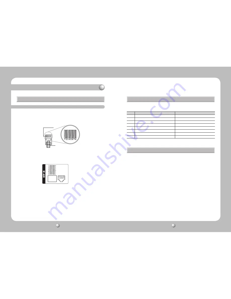
- Connect an RJ-45 plug to the UTP cable on the SPU-400 4-channel power supply.
- The following pin alignment complies with the communication cable standards and is
provided for your convenient installation.
RJ-45 Connector Wiring Chart for Video Input (SPU-400
↔
SPU-400R)
- Connect an RJ-45 plug to the UTP cable on the SPU-400.
- Connect the RJ-45 plug to the UTP IN connector on the SPU-400R.
- Connect the AC power plug to the AC Inlet on the SPU-400R.
- Double check the UTP cable connection, and then turn on the power switch on the back of
the SPU-400R. The camera starts operating as the front status LED turns green.
- Turn on the power switch on the front panel of the SPU-400R, and check if the front LED of
a video channel turns green. Check the video signaling status at the DVR end.
- This equipment is indoor use and all the communication wirings are limited to inside of the
building
- Connect the RJ-45 plug to the UTP IN port on the SPU-400R.
- Please refer to the following pin description for the channel distribution.
- Please remember the description above may differ from your camera’s pin description.
3-2. Installing the SPU-400R and Connecting UTP Cable
3-3. SPU-400R Connector Wiring Chart
3-4. Connecting &Operating the SPU-400R
3. Product Parts and Peripheral Device Connection
No.
Color
Function
1
White
Camera 2, (+)
2
Orange
Camera 2, (-)
3
Green + White
Camera 3, (+)
4
Blue
Camera 1, (-)
5
Blue + White
Camera 1, (+)
6
Green
Camera 3, (-)
7
Brown + White
Camera 4, (+)
8
Brown
Camera 4, (-)
Copper Connector
UTP Coating


